
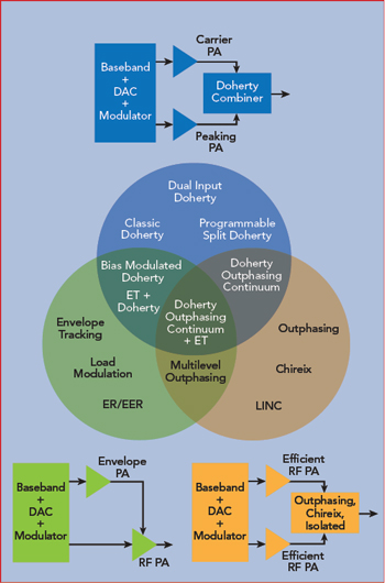
Figure 1 Amplifier linearization options using post-source, predicted/synthesized composition schemes.
The Doherty power amplifier (PA), invented almost 100 years ago, is used in an increasing number of radio transmitter applications to improve energy efficiency, with numerous ways to build the PA. This article begins with an overview of linearization and efficiency enhancement and, against that backdrop, highlights the associated challenges and some of the numerous solutions. Finally, there is an alternative design flow, illustrated with a case study providing insight into the design and how to achieve the best performance-cost compromise.
LINEARIZATION TECHNIQUES
The four key technical performance parameters in a transmit (Tx) RF front-end (RFFE) are the efficiency, output power, linearity and bandwidth. The latter three are often dictated by system requirements, such as a communications standard. The former, (energy) efficiency, is the differentiator. All other performance parameters being equal, a higher efficiency for a front-end is preferred.
Devices used in the RFFE have imperfect linearity characteristics, preventing them from being fully utilized merely as drop-in components. The linearity of a Tx RFFE can be improved by implementing a linearization scheme. Typically, this will increase the raw cost of a Tx RFFE, trading that for a combination of efficiency, linearity and output power improvement. Numerous linearization methods have been published, stretching back at least to the feedforward1 and feedback2 patents. Arguably, the use of nonlinear predistortion dates similarly to the invention of companding.3 These schemes may be classified according to their modus operandi (see Figure 1 and Table 1).4 One way of dividing the linearization pie is to identify whether a scheme predicts or extracts its unwanted signal and whether that unwanted correction is applied before or after its creation. Classification is useful to understand the general properties and identify the best approach for the application.
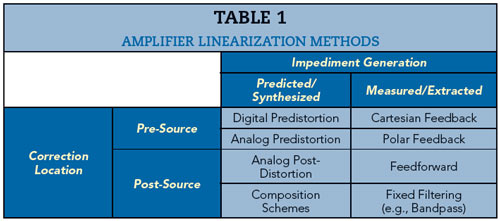
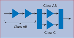
Figure 2 Simplest implementation of the Doherty amplifier.
Feedforward is an example of a measured, post-correction scheme; feedback is a measured, pre-correction scheme; and predistortion is a predicted, pre-correction scheme. Predictive schemes rely on the unwanted signal being generated, which can potentially be onerous in wider band and lower power systems for digital predistortion (DPD). On the other hand, predictive schemes do not require that distortion exists and can, potentially, eliminate distortion completely.
Missing from these examples is a whole class of linearization techniques using predictive post-correction. This family of techniques has also been heavily researched and documented over the last 100 years. Outphasing,5 envelope6 and Doherty7 transmitters, along with their hybrids by Choi,8 Andersson9 and Chung10 are examples of such techniques, except they have been primarily marketed for efficiency enhancement rather than as linearization techniques. In their purest forms, envelope and outphasing schemes construct their signals from efficiently generated, nonlinear components, using multiplication and summing of their paths, respectively. A Doherty comprises a reference path, referred to as the “main” or “carrier,” and an efficiency path, named the “peaking” or “auxiliary.” A more comprehensive mathematical analysis of the Doherty design is beyond the scope of this article and is available in a plurality of texts. For further information, the reader is especially referred to Cripps.11
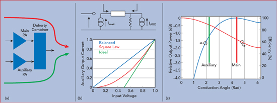
Figure 3 Doherty amplifier challenges: combiner amplitude and phase matching (a), auxiliary amplifier current response (b) and power-efficiency trade-off (c).
DOHERTY IMPLEMENTATIONS
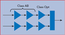
Figure 4 Digital Doherty amplifier, where the main and auxiliary amplifier operating class is digitally controlled.
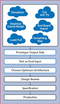
Figure 5 Measurement-aided design flow for a digital Doherty amplifier.
Arguably, the most common and often quickest starting point for a Doherty amplifier design is the “zeroth embodiment” (see Figure 2), comprising a
- Fixed RF input to the final stage power splitter.
- Main and auxiliary amplifiers, differently biased (e.g., using class AB and class C).
- Doherty combiner made from a quarter-wavelength transmission line.
In most applications, this architecture does not provide sufficient power gain - at least not from a single, final stage - and additional gain stages are cascaded ahead of the power splitter. Criticism of this most commonly used implementation include
- No method for compensating gain and phase variations in any domain after the design is frozen.
- Both the efficiency and output power are traded-off because of the bias class. In effect, the class C bias, an open loop analog circuit, is driving this.
- Efficiency enhancement is limited to a single stage. With a multistage cascade, this limits the performance improvement, especially as gain diminishes at higher frequencies.
From another perspective, the Doherty engine is an open loop scheme, with several key functional mechanisms derived from the bias points of the transistors. Once the other variables are defined (e.g., phase offsets, splitter design, etc.), only one or two handles are provided, upon which multiple critical adjustments rely.
Challenges
One of the ways the Doherty improves efficiency is load modulation. The engine that drives that is the difference in output currents, sourced into the combiner from two or more amplifiers. Since the engine can only approximate the Doherty operation, the challenge for the designer is to enable the engine to approximate it with the best, but still appropriate, cost-performance paradigm. Some of the potential hindrances or impediments to Doherty performance are 1) the amplitude and phase matching of the signals incident to the combining node, especially over frequency (see Figure 3a). Deviation from the ideal degrades efficiency and output power. Potentially, this can be more destructive, as the devices are intentionally not isolated, with the efficiency enhancement relying on their mutual interaction through the combiner. 2) Ideally, the auxiliary path of the Doherty engine exhibits a dog leg or hockey stick characteristic (see Figure 3b). Failure to achieve the ideal is often the primary reason for not realizing the famous efficiency saddle point. As the characteristic tends from the ideal to a linear response, the Doherty amplifier increasingly behaves like its quadrature-balanced relative - albeit with a non-isolated combiner - especially its efficiency performance. 3) The commonly used “differential biasing” of the main and auxiliary operating in class AB and class C, respectively, forces the output power and efficiency of both amplifiers to be degraded (see Figure 3c). As Cripps showed,11 the continuum of quasi-linear amplifier classes from A to C, which theoretically operate with sinusoidal voltages across their sources, varies their respective maximum output power and efficiency characteristics. At the same time, if biasing is used to create the difference engine, as is the case in the classical Doherty embodiment, there is intrinsically a trade-off between output power and efficiency. Simultaneously, differential biasing increases the Doherty effect, yet decreases the achievable performance.