
With the full approval of Release 15 by the 3GPP in June 2018, 5G commercial networks were quickly launched in the U.S. (Verizon and AT&T) and South Korea (KT, LG UPlus and SK Telecom) by the end of the year. In 2019, the industry will see increased activity with many 5G launches and a major shift in emphasis from LTE to 5G networks. Since 5G testing standards are still not completely defined, base station and handset manufacturers, wireless carriers and regulators have to come together quickly around the world and agree on how to install, verify and maintain commercial 5G networks. At this critical point in time, Microwave Journal reached out to nine leading test & measurement companies in the industry and compiled their information about the challenges and solutions currently available in the area of 5G over-the-air (OTA) testing. The companies included Anritsu, EMITE, ETS-Lindgren, Keysight, MVG, National Instruments (NI), NSI-MI, Rohde & Schwarz (R&S) and Boonton, Noisecom.
5G TEST CHALLENGES
Anritsu outlined the primary challenge due to the fundamental differences in the technology used in 5G testing - like mmWave frequencies, massive arrays of antennas, beamforming and dynamic physical layer attributes - so trying to apply LTE test methods to 5G networks will not work. Countries in different regions of the world are using different frequency bands for 5G deployments, and in addition to showing compliance with the 3GPP 5G New Radio (NR) standard, many countries require compliance with local government regulations.
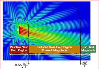
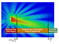
Figure 1 R&S provided antenna radiation pattern in the near-field, far-field, and Fraunhofer distances.
R&S wrote in a recent Microwave Journal article that 5G deployment will rely on the performance of highly integrated solutions combining the modem, RF front-end and antenna. The challenge is to define new methods and setups for performance evaluation, as RF test ports tend to disappear and beam steering technologies require system-level testing. In this context, both antenna and transceiver performance criteria must be measured OTA: effective isotropic radiated power (EIRP), total radiated power (TRP), effective isotropic sensitivity (EIS), total isotropic sensitivity (TIS), error vector magnitude (EVM), adjacent channel leakage ratio (ACLR) and spectrum emission mask (SEM) are some of the critical measurements needed.
R&S continued with the point that assessing these OTA raises the critical question of the required measurement distance. Antenna characteristics are usually measured in the far field (see Figure 1). Using direct far-field probing and applying the Fraunhofer distance criterion (R = 2D2/λ), a 75 cm massive MIMO device under test (DUT) radiating at 2.4 GHz should be evaluated in a chamber with at least 9 m range length. Even a 15 cm smartphone transmitting at 43.5 GHz needs a 6.5 m testing distance. This distance is required to create a region encompassing the DUT, where the impinging field is as uniform as possible and approaches a plane wave with phase deviation below 22.5 degrees, known as the quiet zone.
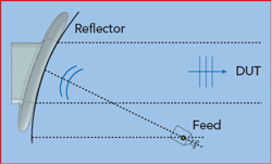
Figure 2 Diagram of how a compact antenna test range operates.
One way to overcome the space constraint of a big chamber is by using a reflector that projects the incoming spherical wave front to a plane wave due to the reflector’s parabolic shape. Using such a reflector is a well-known method for mmWave OTA setups and is called a compact antenna test range (CATR). The principal is shown in Figure 2.
Anritsu said a key companion to EIRP is gated sweep. With a gated sweep, the user can define which portion of the 5G transmission to measure. This is important because 5G NR signals can be configured through the slot configuration parameter in 55 different TDD Tx/Rx ratios in a 10 ms frame. By gating only the subframe or symbol of interest, the user can ensure that only the RF of the downlink is measured. This will give a more true representation of the RF energy being radiated into the atmosphere.
ETS-Lindgren and Anritsu both noted that significant changes are needed for meaningful EMC tests on 5G devices. TRP is a common measurement required by regulatory standards to ensure radios are not transmitting too much power. Because the signal is transmitted from one isotropic transmitter that is radiating energy evenly across an entire sector in LTE, it is easy to make a measurement on the total power at the radio and determine if the atmospheric energy is within safe limits. ETS-Lindgren stressed the challenge with beamforming as shown in Figure 3; there is no easy way to measure the energy at any single point and know how much power is being transmitted into space since it is directional. With side lobes and back lobes, the only way to measure the TRP is to integrate the power in a 360 degree sphere around the entire antenna. While this can be done, it can be expensive and time consuming.
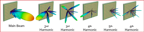
Figure 3 ETS-Lindgren provided radiation pattern for a 28 GHz phased array showing the main beam to the left and the first through sixth harmonic radiation patterns going left to right.
Anritsu commented that as the industry starts to converge on installation and maintenance best practices, the next challenge will be defining procedures and finding equipment that will make the test as accurate, efficient and affordable as possible. This will require test vendors to react quickly to test needs and be ready with new generation hardware that can meet the challenge.
OTA TEST METHODS
Keysight explained the test methods well, stating that when defining an OTA test strategy, it is important to have a good understanding of what will be tested, how it should be tested and what are the appropriate test methods for the different test cases. In the consumer market, testing will be done on modems, antennas, subsystems and fully assembled end-user devices. Base stations will follow a similar testing workflow. A typical testing cycle starts from R&D through conformance and device acceptance testing.
Typically, tests can be categorized into conformance and performance tests. Conformance tests are mandatory tests that need to be completed to release a device. Conformance tests are a key requirement and involve connecting a device to a wireless test system and performing the required 3GPP tests:
- RF transmission and reception performance - minimum level of signal quality.
- Demodulation - data throughput performance.
- Radio resource management (RRM) - initial access, handover and mobility.
- Signaling - upper layer signaling procedures.
Keysight stated that modem chipsets, antennas, base stations and integrated devices will require a mix of conducted and OTA tests. Most frequency range 1 (FR1: 450 MHz to 7.125 GHz) tests will be done using conducted measurements, while 3GPP has defined all frequency range 2 (FR2: 24.25 to 52.6 GHz) conformance tests to be done using OTA test methods.
To date, there are three OTA test methods approved by 3GPP, according to Keysight:
- Direct Far Field (DFF): The measurement antenna is placed in the far field. The far-field or Fraunhofer distance begins at 2D2/λ, where D is the maximum diameter of the radiating elements and λ is the wavelength. This is where the angular field distribution stops evolving. The direct far-field method can perform the most comprehensive tests, measuring multiple signals, but can also result in a longer test range at mmWave frequencies.
- Indirect Far Field (IFF): A far-field environment is created using a physical transformation, typically involving a parabolic reflector to collimate the signals transmitted by the probe antenna. This method is limited to measuring a single signal angle of arrival/departure but provides a much shorter distance with less path loss. This test method is accomplished using a CATR.
- Near Field to Far Field Transformation (NFTF): Phase and amplitude of the electrical field are sampled in the radiated near-field region, and the far-field pattern is computed. This method is also limited to a single line-of-sight transceiver measurement.
According to R&S, as of early January 2019, 3GPP specified a number of transmitter and receiver tests in the 3GPP TS38.521‐3, which is the NR User Equipment (UE) conformance specification for radio transmission and reception where “−3” refers to part 3 and means FR1 and FR2 interworking operation with LTE, basically Non-Standalone (NSA) sub-6 GHz as well as NSA mmWave.
For mmWave, testing becomes more difficult since everything will need to be tested OTA and a black box approach has to be assumed. This means that achievable measurement uncertainties (MU) and test tolerances (TT) will need to be much wider than in sub-6 GHz FR1 conducted testing. It is an ongoing discussion in 3GPP which MUs are acceptable and what TT to use for FR2. Until this is fixed by 3GPP, spec compliant RF conformance tests for FR2 are not practical.
For Standalone (SA) deployment scenarios, the matching 38.521 parts 1 (sub-6 GHz) and 2 (mmWave) are more advanced, even though the first 5G NR deployments early this year will be NSA. On top of this, the specifications for performance tests (38.521-4) and RRM test requirements (38.533) are not yet ready for NSA.
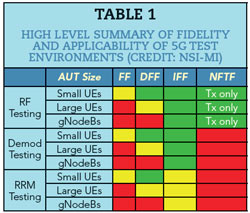
Table 1, created by NSI-MI, summarizes the applicability of the test environments to different types of testing and different antenna sizes. Colors indicate quality of the solution in terms of SNR, utility, cost, etc.
Emite said there is no single OTA test method capable of providing the answers to all of the problems and challenges we have today. Therefore, industry will need to adopt a variety of methods. Some companies have shown that there are benefits to rich isotropic systems for obtaining some key performance parameters, while directionality is needed to address the evaluation of other 5G features. Simultaneously testing at both near- and far-field distances, low and high frequencies, large and small form factors may also be needed.
ETS-Lindgren added that engineers often ask if a single do-it-all chamber for 5G OTA, EMC and cable replacement tests could be designed. They find there are too many compromises each method would impose on the others to make this a cost effective approach. Measurement uncertainty requirements drive optimization in different directions for each type of test. Consider the additional absorber and measurement antennas that would need to be moved in and out of a traditional 3 m EMC chamber quiet zone to transition between EMC and far-field OTA requirements. The transition time and costs associated with a do-it-all test chamber will mostly outweigh the benefits.
OTA PRODUCT OFFERINGS
Here are some of the OTA solutions being offered by these leading test & measurement suppliers:
Anritsu’s New Solution
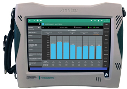
Figure 4 Anritsu’s Field Master™ Pro MS2090A handheld solution.
With the launch of the Field Master™ Pro MS2090A at MWC Barcelona 2019 in February, Anritsu introduces the first field portable instrument with continuous frequency coverage for sub-3 GHz, sub-6 GHz and mmWave 5GNR measurements (see Figure 4). The Field Master Pro MS2090A has been developed in close cooperation with all leading 5G base station manufacturers, as well as being used to install the first commercial 5GNR networks. This should have a significant impact on the testing market to have this capability in a handheld unit.
The key features of the Field Master Pro MS2090A are:
- Continuous frequency coverage from 9 kHz to 9, 14, 20, 32, 44 or 54 GHz.
- 100 MHz analysis bandwidth for current 5G deployments.
- 5G NR demodulation capabilities.
- RTSA for interference hunting.
- Built-in EIRP and gated sweep for transmission testing.
- 10.1 in. multi-touch screen user interface.
EMITE Solutions

Figure 5 EMITE’s F-Series 200 MHz to 110 GHz hybrid Anechoic-reverberation chambers.
For a small company in this space, EMITE offers a broad range of solutions. The EMITE PT-Series is a small reverberation chamber which serves as a simple go, no-go mmWave SISO OTA test and some non-signaling production OTA tests for up to eight simultaneous DUTs of up to 15 cm.
Their E-Series is a medium-size reverberation chamber capable of providing fully-automated 5G OTA testing of some isotropic key performance indicators, as well as latency and throughput. The E-Series chambers can easily accommodate many carriers with 4G and 5G technologies, with up to 8x8 MIMO, and can make use of channel emulators for 5G channel modeling. A unique solution from EMITE, these can also be cascaded to test massive MIMO and E2E OTA tests, representing a first step into 5G OTA signaling testing.