
One of the critical and costly components in digital cellular communication systems is the RF power amplifier. Theoretically, one of the main concerns in an RF power amplifier design is the nonlinear effect of the amplifier. Quantitatively, no explicit relationship or expression currently exists between the out-of-band emission level and the nonlinearity description related to the third-order intercept point (IP3 ). Further, in experiments and analysis, it was discovered that, in some situations, using only IP3 is not accurate enough to describe the spectrum regrowth, especially when the fifth-order intercept point (IP5 ) is relatively significant compared to the third-order intermodulation. In this article, the nonlinear effect of an RF power amplifier in a time division multiple access (TDMA) (IS-54 Standard) system is analyzed and an expression is presented of the estimation of the out-of-band emission levels for a TDMA power spectrum in terms of the IP3 and the IP5 , as well as the power level of the signal. This result will be useful in the design of RF power amplifiers for TDMA wireless systems.
In recent years, TDMA has been recognized as one of the most efficient and reliable schemes for cellular radio communications.1,2 As in other communication systems, one of the critical and costly components in TDMA systems is the RF power amplifier. One of the main concerns in RF power amplifier design is its nonlinearity, which can degrade the quality of the TDMA signal, increasing bit error rate and interference to adjacent channels. The level of nonlinearity is specified in the IS-54 standard3 by the out-of-band power emission levels. It is also called spectrum regrowth. Traditionally, the nonlinearity of an RF amplifier is described by using IP3 .4,5 In experiments and analyses, it was discovered that, in some cases, using only IP3 is not accurate enough to describe the spectrum regrowth, especially when the fifth-order intermodulation is relatively significant compared the third-order intermodulation. Quantitatively, to the best of our knowledge, there is no explicit relationship or expression between the out-of-band emission level and the traditional amplifier nonlinearity description for the TDMA signal amplification. The lack of such a relationship makes it difficult for RF power amplifier designers to choose components. In an early effort, the nonlinear effect of an RF power amplifier on code division multiple access (CDMA) systems was analyzed.6,7 Continuing this effort into developing the spectrum analysis approach for TDMA signals, the expressions of the estimated out-of-band emission levels for TDMA signal are derived, and the relationship between an amplifier's out-of-band power emission levels and its nonlinearity parameters, IP3 and IP5 , is presented. The results presented in this article allow RF amplifier designers to specify and measure the TDMA signal amplifiers using simple IP3 and IP5 descriptions. The expression turns out to be simpler and easier to use in the case where IP5 may be ignored. In addition, a spectrum comparison between the simulated and predicted results is presented.
MODEL DESCRIPTION
The TDMA Signal Mathematical Model
Generally, the mathematical model of the IS-54 TDMA signal can be presented as3

where
|
h(t) |
= |
baseband filter that has a linear phase and square root raised cosine frequency response |
|
A |
= |
constant, depending only on the minimum TDMA symbol energy |
|
Φn |
= |
absolute phase corresponding to the n-th symbol interval |
|
Ts |
= |
symbol period, equal to 41.15 µs for IS-54 standard |
|
fc |
= |
carrier center frequency |
|
|
= |
initial phase |
|
Re{x} |
= |
real part of {x} |
|
g(t) |
= |
|
Pg = A2 Rs |H(f)|2 (2)
where
|
Rs = 1/Ts |
= |
symbol rate |
|
H(f) |
= |
frequency response of the baseband filter |
Since the spectrum of a bandpass signal is directly related to the spectrum of its baseband envelope, the PSD of a TDMA signal, s(t), can be expressed as4

where s(t) = Re{g(t) * ejωct } was given in Equation 1.
Equivalently, the mathematical model of s(t) can also be described as
s(t) = r(t)cos (t)cos(2πfc t + 0 ) r(t)sin (t)sin(2πfc t + 0 )
= r(t)cos[2πfc t + (t) + 0 ] (4)
where
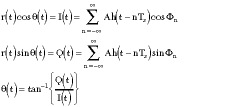
and  is the baseband envelope of s(t). Its Fourier transform can be derived from the PSD of g(t), Pg through a lengthy derivation

where F{r(t)} is the Fourier transform of {r(t)}.
A Power Amplifier's Mathematical Model
Generally speaking, a practical amplifier is only a linear device in its linear region, meaning that the output of the amplifier will not be exactly a scaled copy of the input signal when the amplifier works beyond the linear region. Considering an amplifier as a functional box, it can be modeled by a Taylor series.4,5 The Taylor series model is only valid for a memoryless nonlinearity function. For a memoryless amplifier with only a few stages, a Taylor series model is fairly good for predicting the nonlinearity. Therefore, the Taylor series is adopted for modeling RF power amplifiers. Using the TDMA signal equivalent mathematical model s(t) of Equation 4, the output of an amplifier can generally be written as
y(t) = O{s(t)} = F[r(t)] cos {2πfc t + (t) + 0 + Φ[r(t)]}(6)
|
O{s(t)} |
= |
operation of amplifier |
|
F[r(t)] |
= |
amplitude to amplitude conversion (AM/AM) |
|
Φ[r(t)] |
= |
amplitude to phase conversion (AM/PM) |
The functions F[r(t)] and Φ[r(t)] are dependent on the nonlinearity of the amplifier and modeling type.
For the memoryless power amplifier, AM/PM conversion causes only a deterministic constant phase shift to be added to the argument of the signal at the output but has no other effect on its phase,8 that is, Φ[r(t)] = ap , which is the constant phase shift. Therefore, Equation 6 becomes
y(t) = 0{s(t)} = F[r(t)] cos (2πfc t + ) (7)
where
= (t) + 0 + ap
Let  (t) = F[r(t)], the Taylor expansion of O{s(t)} can be used to determine (t). Generally, the Taylor model of an RF amplifier can be written as

Here, only the odd-order terms in the Taylor series are considered, since the spectra generated by the even-order terms are at least fc away from the center of the passband; the effects from these terms on the passband are negligible. Furthermore, as a linear amplifier, the third- and fifth-order terms dominate in Equation 8 for distortion. Therefore, in this analysis, the following model is used for an RF amplifier

Substituting the input passband signal s(t) = r(t)cos
(2πfc t + ) into y(t) of Equation 9 (after manipulation) produces

where

with

Here, the coefficient a1 is related to the linear gain G of the amplifier, and the coefficients a3 and a5 are directly related to IP3 and IP5 , respectively. It can be proven after a lengthy derivation that the expression for these coefficients becomes
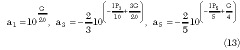
From Equations 10 to 13, it can be seen that an amplifier's output y(t) is a function of G, IP3 , IP5 and the input signal s(t). Consequently, using Equation 10 and the PSD of s(t) in Equation 3, the PSD of y(t) can be calculated and the power emission levels can be determined. Therefore, all of the nonlinear effects of the amplifier with the TDMA signals can be evaluated.
THE POWER SPECTRUM DENSITY (PSD) OF THE AMPLIFIED TDMA SIGNAL
Now, the PSD of y(t) can be calculated. Since y(t) = (t) cos(2πfc t + ), the PSD of y(t) can be determined by the PSD of (t) as4,5

and then the PSD of (t) can be derived by Wiener-Khintchine Theorem as4

By definition, R (*) is expressed as

where E{x} is the mathematical expectation of {x}.
Since
(t) = ã1 r(t) + ã3 r3 (t) + ã5 r5 (t)
P (f) can be expressed in terms of the Fourier transform of r(t) through a lengthy derivation as
|
P |
= |
F{R | |
|
|
= |
ã1 2 F{r(t)}F{r(t)}+2ã1 ã3 F{r(t)}F{r3 (t)} | |
|
|
+ |
2ã1 ã5 F{r(t)}F{r5 (t)} | |
|
|
+ |
ã3 2 F{r3 (t)}F{r3 (t)}+2ã3 ã5 F{r3 (t)}F{r5 (t)} | |
|
|
+ |
ã5 2 F{r5 (t)}F{r5 (t)} |
(17) |
where F{r(t)} = A s|H(f)| was obtained in Equation 5.
Let

as a result
F{r(t)} = A s P1 , F{r3 (t)} = (A s )3 P3
and
F{r5 (t)} = (A s )5 P5
where
P3 = P1  P1 P1 , P5 = P1 P1 P1 P1 P1
in which * denotes a convolution operator. Also, the linear portion of the amplifier output P0 can be described as4,5

Substituting P1 , P3 , P5 and P0 into Equation 17 produces
By the relationship between Py (f) and P (f) in Equation 14, the final result of the power spectrum Py (f) of y(t) in terms of G, IP3 , IP5 and P0 becomes
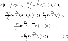
where
fc = carrier center frequency
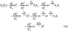
If IP5 is ignored, Equation 20 becomes
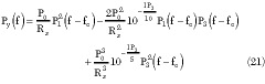
Thus, Equation 21 is a special case of Equation 20. It provides a simpler and easier result to use in the case where IP5 may be ignored.
Several observations are made by inspecting Equation 21: the first term

corresponds to the linear output power density; the remaining terms in Equation 21 are caused by the nonlinearity. In other words, these remaining terms are due to the intermodulation. For a linear amplifier, the intermodulation is usually much lower than the linear output power. Therefore, the intermodulation does not affect the passband spectrum significantly.
With the explicit power spectrum of the output TDMA signal, the out-of-band spurious emission power may be calculated in a particular frequency band. It is this power that is used in IS-54 to specify the limit for the out-of-band emission level. To keep the result easy to use, only IP3 is considered here.
Let a frequency band be defined by f1 and f2 outside the passband. Using the results from Py (f) of Equation 21, the emission power level within the band (f1 , f2 ), denoted as PIM3 (f1 , f2 ), can be determined easily by
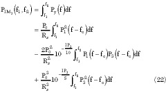
Equation 22 can also be expressed as

where
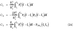
In most design procedures, a designer is concerned with the required IP3 for a given out-of-band emission level. To obtain the desired IP3 , Equation 23 is solved for IP3 with given PIM3 (f1 ,f2 ), which yields

where C1 , C2 and C3 are given in Equation 24.
This result provides a direct relationship between the out-of-band emission power of a TDMA signal power amplifier and its IP3 . With a given required IP3 , the power amplifier design for a TDMA signal becomes a conventional RF power amplifier design.
DESIGN EXAMPLE AND COMPARISON WITH SIMULATIONS
In this example, the result shown in Equation 25 is used to design a 4 W amplifier, which complies with the out-of-band emission level limit requirement proposed for TDMA standard amplifiers. The out-of-band emission level limits required in IS-54 are given as follows: the total TDMA signal bandwidth is 30 kHz. In the band of (fc + 18 kHz) to (fc + 47.5 kHz), the suppression level between the output power and emission power at 0.72 kHz bandwidth must be larger than 45 dB.
For this amplifier, P0 = 4W and for the (fc + 18 kHz) to
(fc + 47.5 kHz) band, the corresponding maximum PIM3 (f1 ,f2 ) is expressed as

For the worst case, f1 and f2 are assumed at the lower edge of [fc + 18 kHz, fc + 47.5 kHz], that is f1 = fc + 18 kHz = fc + 0.018 MHz and f1 = fc + 18 kHz + 0.72 kHz = fc + 0.01872 MHz.
Then, from Equation 25, the required IP3 becomes IP3 = 48.6 dBm. For the band described above, in order to meet the IS-54 requirement, the TDMA amplifier must have an IP3 of at least 48.6 dBm.
As mentioned before, IP5 is not given in the data book. Fortunately, IP5 could be measured through a two-tone test.9 Therefore, without loss of generality, IP5 can be assumed as 45 dBm at the same output power level, and the linear gain G of the power amplifier can be normalized to 1. Thus, the nonlinearity of the power amplifier can be simulated according to Equations 9 and 13, where G = 1, IP3 = 48.6 dBm and IP5 = 45 dBm.
In this simulation using MATLAB software, the TDMA signals were generated in accordance with the TDMA standard IS-54-B.3 Figure 1 shows the power spectrum predicted from this example compared to the spectrum given by simulation. The simulated RF amplifier spectrum agrees with the analytically predicted spectrum in both the passband and shoulder area.
The predicted result using only IP3 vs. both IP3 and IP5 is shown in Figure 2. It can be seen clearly that a better fit exists when both IP3 and IP5 are used vs. IP3 only.
|
|
|


CONCLUSION
It was assumed traditionally that the effects of the fifth- or higher order intermodulation could be ignored. However, if the fifth-order intermodulation is relatively high compared to the third-order intermodulation, the out-of-band emission power levels caused by fifth-order intermodulation can be significant.
In this article, a theoretical method is proposed to predict the output power spectrum of a TDMA standard RF power amplifier so that the traditional nonlinearity parameter IP3 and additional parameter IP5 are linked directly with out-of-band emission levels. This analysis makes it possible for RF power amplifier designers to use a conventional approach to design RF power amplifiers for TDMA signals. In addition to the results presented in this article, this derivation approach can be applied to out-of-band emission level analysis for other communication standards.
References
1. David D. Falconer, Fumiyuki Adachi and Bjorn Gudmundson, "Time Division Multiple Access Methods for Wireless Personal Communications," IEEE Communications Magazine, January 1995, Vol. 33, No. 1,
pp. 5057.
2. Jay E. Padgett, Christopher G. Günter and Takeshi Hattori, "Overview of Wireless Personal Communications," IEEE Communications Magazine, January 1995, Vol. 33, No. 1, pp. 2841.
3. EIA/TIA Interim Standard IS-54-B, Cellular System Dual Mode Mobile Station - Basestation Compatibility Standard, April 1992.
4. Leon W. Couch II, Digital and Analog Communication Systems, Prentice-Hall Inc., New Jersey, 1996.
5. Theodore S. Rappaport, Wireless Communication Principle and Practice, Prentice-Hall Inc., New Jersey, 1996.
6. Qiang Wu, Heng Xiao and Fu Li, "Linear RF Power Amplifier Design for CDMA Signals: A Spectrum Analysis Approach," Microwave Journal, December 1998, Vol. 41, No. 12, pp. 2240.
7. Heng Xiao, Qiang Wu and Fu Li, "Nonlinear Distortion Analysis on CDMA Communication Systems," IEE Electronics Letters, April 1998, Vol. 34, No. 8, pp. 730731.
8. John Minkoff, "The Role of AM/PM Conversion in Memoryless Nonlinear Systems," IEEE Transactions on Communications, February 1985, Vol. COM-33, No. 2, pp. 139144.
9. Heng Xiao, Qiang Wu and Fu Li, "Measure A Power Amplifier's Fifth-order Interception Point," RF Design, April 1999, pp. 5456.
 Chunming Liu received his BS and MS degrees in electrical engineering from Northwestern Polytechnic University, China, in 1995 and 1998, respectively. He is currently a PhD candidate in the department of electrical and computer engineering at Portland State University. His research interests include wireless communications, signal spectral analysis, and image and video signal processing.
Heng Xiao received his BS and MS degrees in computer and system engineering from Xiamen University, China, in 1982 and 1987, respectively. He also received his MS and PhD degrees in electrical and computer engineering from Portland State University in 1994 and 1999, respectively. Dr. Xiao is currently a system engineer with Lucent Technologies. Prior to that, he worked for Atlas Communications Inc. and Metro One Telecommunications Inc. His research interests include wireless communication and multi-channel signal processing.
Fu Li received his BS and MS degrees in physics from Sichuan University, China, in 1982 and 1985, respectively. He received his PhD degree in electrical engineering from the University of Rhode Island in 1990. He is a professional engineer licensed in the state of Oregon. Since 1990 Dr. Li has been with Portland State University, where he is currently a professor of electrical engineering with indefinite tenure. He worked at Philips Laboratories and Prime Computer prior to 1990. He has been consulting for a number of companies, including Intel Corp., which he visited full-time during his sabbatical leave. His research interests include wireless and network communications, and signal, image and video processing. He has published over seventy papers. Dr. Li received a Pew Teaching Leadership Award at the Second National Conference on Training and Employment of Teaching Assistants in 1989, and is also a recipient of several IEEE awards.
Qiang (Chung) Wu received his BSc and MSc degrees from Shanghai Jiao Tong University, Shanghai, China, in 1982 and 1984, respectively, and his DSc degree from Washington University, St. Louis, MO, in 1989, all in electrical engineering. From 1989 to 1994 he was with Communication Research Laboratory, McMaster University, Hamilton, Canada, as a senior research staff and adjunct professor. From 1994 to 1997 he worked at Celwave, a division of Alcatel North America, as an engineering manager for RF repeater and digital subsystem. Currently, as a senior staff system architect, he is working at Platform Networking Group of Intel. His research interests include RF and wireless system design, DSP for broadband access and array signal processing.