
CHALLENGES FOR 5G OTA TESTING
Fully-integrated antenna arrays
In addition to a densely antenna-populated layout, illustrated in Figure 4, and unlike previous generations, 5G UE antenna arrays do not provide access to their RF ports due to small form factor and higher frequencies for some bands. Testing connector-less antenna arrays is an obvious challenge, which forces RF tests and calibrations to be performed OTA in a well-controlled environment. Phase calibration between the chains is typically required in addition to signaling performance tests and power measurements. The fact that coupling may occur and the limitations of the testing enclosure make the coherent calibration of each RF chain not necessarily leading to optimal beams. The up- or down-conversion for operating at mmWave frequencies further complicates the testing equipment.
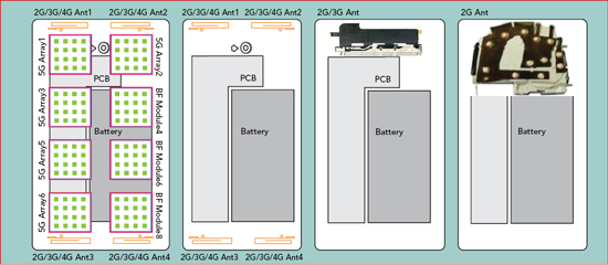
Figure 4 The antenna layout evolution on UEs.
DUT form factors
Each DUT form factor type has specific requirements and restrictions. Chipset 5G OTA measurements can be defined as the test that provides the chipset RF performance evaluation in the real SA environment.5 It is good that chipsets are small since the mmWave wavelengths of 5G frequencies are also small, and therefore the issues with large far-field distances are minimized. The problem arises due to the fact that the chipsets usually do not have RF connectors and are also very fragile. Two other chipset-specific challenges for 5G OTA testing are the need to accurately control temperature and humidity cycling within the chamber due to the chipset being sensitive to environmental conditions and the fact that for mass production chipsets may need to be measured in the form of panels. With each panel containing a lot of similar types of chipsets, their accurate and individual 5G OTA testing becomes a very challenging task. Controlling the temperature and the humidity within any OTA test environment is also a challenging task, and only two companies have announced such feature at their test systems to date, R&S and EMITE.
5G OTA UE testing is thought to be, at least initially, compatible with legacy 4G technologies. While it has been proposed that 4G OTA methods should be attempted first for the new 5G devices, it is also clear that 5G OTA testing will further be complicated if we have to also support 4G OTA testing simultaneously.
gNodeB testing, in addition to their associated larger size, also requires phase coherency calibration, which is currently a concern due to the large number of channels. The specific OTA measurements challenges of high directivity beam performance, not only for the gNodeB end but also for the 5G UE end, deserve its own section in this technical feature.
Spatial agility
Spatial intelligence is another key performance aspect of 5G. The 3GPP has defined centered and off-center KPIs for static beams, but the beam dynamics are an inherent part of 5G. Processes such as beam searching, beam matching, beam tracking, beamforming or beam scheduling, among others, become essential when the UE moves dynamically. When the gNodeB incorporates massive MIMO, the spatial non-stationary property, the angular spreads and the 3D spatial properties cannot be ignored. Since the number of probe antennas is large, the channel between different probe antennas has a strong correlation, and removing the impact of the channel correlation across gNodeB antennas and probes remain an issue of concern.
Finally, the addition of multiuser bidirectional channels introduces yet additional challenges to the OTA test. Interestingly enough, the whole 5G gNodeB-UE end-to-end (E2E) set seems to be attracting the most attention, as it is the pair that provides a specific user-performance. Extraordinarily complex cascaded chamber sets are being proposed for this type of testing, aiming at getting accurate and realistic KPI evaluation vs. range when using power-fix connectorless gNodeBs in one end and a moving UE on the other end. In this type of OTA test setup, shown in Figure 5, for NR beam steering, beamforming or baseband beam tracking algorithms performance testing, real-time throughput, latency and mobility tests are being proposed. One chamber captures the 5G signals coming from the gNodeB and redirects them to a channel emulator and an attenuator matrix, which in turn attenuates and re-route the signals to a second chamber, an RC or AC, in which the 5G UE is located. This represents a breakthrough over previous single-chamber OTA test setups, with a lot more complexity, associated required expertise and cost.
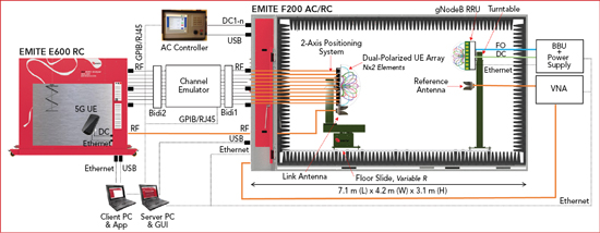
Figure 5 gNodeB-UE E2E 5G OTA testing vs. range with two cascaded chambers.
Channel modeling
Realistic channel modeling represents yet another key aspect of 5G OTA testing. Several studies have found some extensibility of the existing 3GPP channel models to be somehow applicable at higher frequency bands up to 100 GHz. The measurements indicate that the smaller wavelengths introduce an increased sensitivity of the propagation models to the scale of the environment, which is to be expected, and show some frequency dependence of the path loss as well as increased occurrence of blockage. Furthermore, the penetration loss is highly dependent on the material and increases with increasing frequency of operation. The shadow fading and angular spread parameters are larger and the boundary between line of sight (LOS) and non-line of sight (NLOS) depends not only on antenna heights but also on the local environment. This has simplified some initial proposals, but the main drawback remains on how to model a signal that is divided into several carriers and MIMO paths which can extend from very different frequency bands. It is expected that FR1+FR2 bands will be successfully combined, providing total user throughputs in excess of tenths of Gbps and new channel modeling challenges.
Conclusion
5G is expected to bring significant benefits for the wireless communications industry, but it also carries the need for drastic changes in the way of how OTA testing is performed today. Performance metrics and cost-efficient ways to measure 5G equipment in a lab that is close to real world use are urgently required. This will necessarily include testing the main beam, testing in the presence of other radios in same channel and testing the communication performance against interference from different directions, evaluating also the dynamic adaptation performance of both sides - the UE and the gNodeB.
While some progress has been made, consensus-based 3GPP standardization is far from reaching the goal, and is currently limiting the scope of what can be achieved in terms of solving the existing real challenges. Failure to meet the expectations is not realistic at this stage of the process, and developing accurate and realistic OTA test methods is also the responsibility of the scientific community. We still have time, but it is rapidly running out.n
References
- Cisco Systems, “Complete Visual Networking Index (VNI) Forecast,” Global Cloud Index (GCI) 2016-2021.
- M. A. García-Fernández et al., “Antenna Gain and Radiation Pattern Measurements in Reverberation Chamber Using Doppler Effect,” IEEE Transactions on Antennas and Propagation, Vol. 6, No. 10, 2014, pp. 5389–5007.
- K. A. Remley et al., “Measurement Challenges for 5G and Beyond,” IEEE Microwave Magazine, July/August 2017, pp. 41–56.
- AT&T, Dish, Sprint, T-Mobile and Verizon, “Operator Requirements for CTIA 5G mmW OTA Test Plan V 1.0,” OTA5GmmWave181121-1, November 2018.
- Y. Qi, “5G Over-the-Air Measurement Challenges: Overview,” IEEE Transactions on Electromagnetic Compatibility, Vol. 59, No. 6, 2017, pp. 1661–1670.