
The selection of a data modulation scheme for radio transmission usually involves a trade among a number of parameters, including communications efficiency (bit error rate (BER) vs. signal-to-noise ratio), bandwidth efficiency and factors affecting the prime power efficiency of the transmitter output stage. If the transmitter is power-starved, as in a communications satellite downlink or a wireless phone return link, then the prime power efficiency can become a dominant concern. Prime power efficiency is usually improved if a constant carrier envelope modulation format can be employed, so long as other modulation values, such as BER performance, are not compromised.
Constant carrier envelope modulation allows the transmitter output stage to operate in saturation, which is maximally efficient as far as prime power efficiency is concerned. Practical alternatives to constant carrier envelope might be the use of predistortion1 to drive a non-constant transmitter output closer to saturation without any attendant regrowth of power spectral sidelobes.
This article discusses a constant carrier output modulation format called Nyquist quadrature frequency shift keying (NQFSK) that presents a perfect quadriphase eye pattern at the transmitter output and achieves excellent spectral containment. Specifically, the spectral containment is very nearly the same as Gaussian minimum shift keying2 (GMSK) with Bb T = 0.2, which attains a remarkably small transmission bandwidth. However the GMSK wave, at Bb T = 0.2, experiences considerable interbit interference (that is, a badly degraded eye pattern) at the transmitter output, which implies that NQFSK is superior overall.
The NQFSK format is based on the well-known Nyquist FSK pulse shaping principle.3 It uses a strictly bandlimited 4-level frequency modulating symbol pulse to achieve a perfect quadriphase eye pattern at the transmitter output. The output of the frequency modulator itself is not, however, perfectly bandlimited, either in theory or in practice. This fact is a well-known consequence of the use of bandlimited Nyquist frequency shift keyed (FSK) driving pulses. Nevertheless, the excellent (though not perfect) spectral containment at the frequency modulator output does justify the Nyquist approach.
NYQUIST FSK VERSUS NYQUIST PSK
The use of strictly bandlimited data pulses, free of intersymbol interference, in the phase shift keyed (PSK) format has been established in the art for some time. These pulses are called bandlimited Nyquist pulses, as exemplified by raised cosine and trapezoidal pulses.4 The use of root raised cosine pulses5 combines Nyquist data transmission with matched filtering against additive white Gaussian noise (AWGN). More recently the expression for root trapezoidal pulses has been placed in closed form.6
The use of bandlimited Nyquist pulses in the PSK format always leads to a non-constant carrier envelope. The choice of a bandlimited Nyquist pulse that minimizes carrier ripple has been the subject of some investigation.7 The spectral degradation from hard-limiting of a non-constant carrier envelope offset quadriphase shift keyed (OQPSK) type data signal has also been the subject of some investigation.8
The possibility of introducing a bandlimited Nyquist driving pulse at the input of a digital FSK modulator was found to be central to the tamed frequency modulation (TFM) concept,9 a partial response signaling format that achieves a remarkably well-contained spectrum. The debut of TFM made it apparent that the use of a bandlimited frequency modulating pulse does not result in a bandlimited frequency modulator output. In addition, it is well-known in theory10 that a data signal cannot simultaneously be bandlimited and constant envelope.
THE NQFSK FORMAT
The NQFSK modulation scheme may be defined, as shown in Figure 1. The input binary data could be raw user data, compressed user data or the output of an algebraic encoder such as a convolutional encoder. The bit interval is Tb and the bit rate Rb = 1/Tb . The encode operation indicated in the first block is a conversion from binary into the quaternary choice of one of four symbol voltage levels to be assigned to a bandlimited Nyquist frequency modulating pulse. A quaternary symbol lasts Ts = 2Tb . The signal that drives the frequency modulator is therefore a strictly bandlimited stream of overlapping symbol pulses. At the output of the frequency modulator is a constant carrier envelope signal whose phase trajectory hits the marks exactly at integer multiples of π/2 at the symbol sampling instants spaced Ts apart. That property defines a perfect quadriphase eye pattern.

|
|


The bandlimited Nyquist FSK modulating pulse is derived from the more familiar class of Nyquist phase modulating pulses, such as raised cosine or trapezoidal. The present NQFSK pulse g(t) will be based on a raised cosine (RC) pulse p(t) with 10 percent excess bandwidth, a choice that optimizes the transmitted spectrum. The Fourier transform of p(t) takes the familiar forms of Equation 1 and the solid curve shown in Figure 2. Following application of the well-known3 frequency-domain modification in Equation 1, the equation for the Fourier transform of the corresponding Nyquist FSK pulse g(t) becomes G(f) as expressed in Equation 2.
P(f) = 1
if | fTs | ≤ .5(1b)
P(f) = .5{1+cos{π[ | fTs | .5(1ß)]/ß}}
if .5(1ß) < *fTs * ≤ .5(1+ß)
P(f) = 0
if | fTs | > .5(1+ß) (1)
G(f) = .5πfTs P(f)/sin(πfTs)
over the interval of interest,
0 < | fTs | ≤ .5 +ß/2 (2)
The pulse g(t) corresponding to Equation 2 is plotted as shown in Figure 3. Note the absence of zero crossings at the synchronous symbol instants. The input to the frequency modulator is a stream of such pulses, each scaled to one of four voltage levels ak corresponding to the kth quaternary symbol exiting the encode block. The four equiprobable values of ak are {1,0,1,2}, whose link to the input binary stream and the output spectrum will be explained here in subsequent sections. The Nyquist property evidences itself at the frequency modulator output through the well-known integral relation between instantaneous frequency and instantaneous phase of any wave. Therefore the instantaneous phase of the signal s(t) will be11
Φ(t) = 2πhΣak q(tkTs ) (3)
where
h = frequency modulation index
q(t) =eg(x)dx), the well-known integral relationship
so that the signal is represented as
s(t) = Ae2πjh akq(tkTs) (4)
where
A = amplitude constant
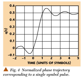
The individual symbol pulse contribution to output phase is plotted as shown in Figure 4. In terms of that figure, the Nyquist criterion for a normalized FSK phase trajectory q(t) is
q(t) intersects zero at all integer values of t ¾ 0
q(t) intersects the value 0.5 at all integer values of t >= 1
The normalized settling value of 0.5 is a standard for continuous phase modulation schemes.11 The scaling of output phase values is controlled by a combination of the values of ak and the modulation index h, which is set to 0.25 here. The function of the Nyquist criterion is to assure that each symbol value influences one and only one synchronous phase transition.
The output phase trajectory corresponding to a specific sequence of ak is shown in Figure 5 in units of π/2. The phase transition from symbol to symbol is either π/2, 0, π/2, or π. That set of transition values is sufficient to convey any binary data stream entering the encode pulse forming network.
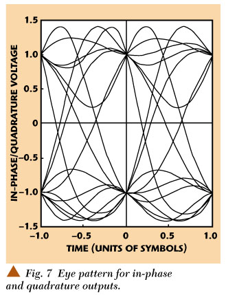
With the output amplitude A set at √2 and a fixed offset of π/4 added to the f (t) of Equation 3 the in-phase and quadrature frequency modulator outputs become the traces shown in Figure 6. Here the salient feature of the eye pattern manifest in the values ±1 at all sampling instants. The eye pattern itself is shown in Figure 7.
At first glance the inter-sample peaks in the eye pattern might suggest that the carrier envelope was not constant. To account accurately for those peaks, however, keep in mind that the criterion for envelope constancy is that the sum of the squares of the in-phase and quadrature components is constant. For example, when the in-phase output intersects zero shortly before t/Ts = 12 the trace for the quadrature output must rise to a peak of √2 in order to maintain a constant envelope amplitude of √2. The narrowness of the interior of the eye pattern also indicates correctly that the detection will be sensitive to sample timing errors.
|
|
|
|
|
|

ENCODING THE BINARY STREAM INTO AK
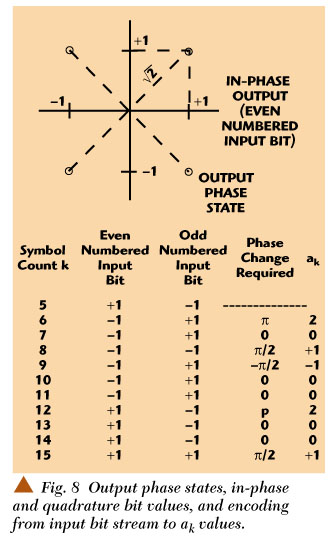
Figure 8 illustrates a possible encoding scheme for the transformation from the input binary bit stream to the sequence ak . The first column of the table shows the even numbered binary input bits. These will be demodulated from in-phase output signal. The second column shows the odd numbered binary bits, identified with the quadrature output signal. The third column shows the output phase change from the previous symbol. Finally, the fourth column shows the corresponding ak needed to produce that change. The sequence of output phases and bits corresponds to the output phase trajectory corresponding to ak and the in-phase and quadrature frequency modulator outputs. Clearly the set of four possible ak is sufficient to generate all possible binary sequences.
There could be other encoding schemes for transforming a binary bit stream into the sequence ak . The ultimate choice of encoding scheme will most likely be dictated by the practical needs of the specific application.
POWER SPECTRAL DENSITY
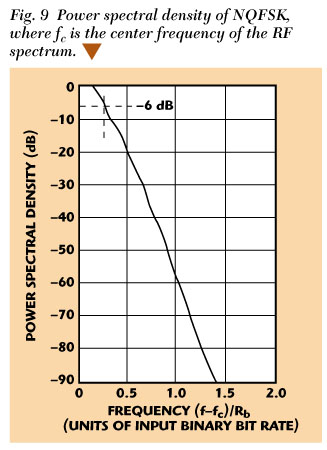
Figure 9 shows the output power spectral density, in closed form,11 with frequency in units of input binary bit rate. The spectrum is clearly better contained than that of such competitive constant envelope schemes as GMSK with bb T = 0.3 as widely implemented in cellular phone systems. Comparison with previously published data2 will show that this output power spectral density is quite similar to GMSK with Bb T = 0.2, which is not widely used because of the excessive intersymbol interference caused by the small value of Bb T.
A second comparison may be made between the output power spectral density and the Fourier transform of p(t), where the normalized frequency fTs = 0.5 corresponds to (ffc )/Rb = 0.25 in the spectral density plot. This comparison provides a partial answer to the question how well can the spectrum of a Nyquist quadriphase signal be contained if the carrier envelope is constrained to be constant. The plotted Fourier transform of p(t) shows that without the constraint of envelope constancy the spectrum is perfectly contained. The output power spectral density plot shows that with the constant envelope constraint the spectrum is still flat-topped, still falls to 6 dB at (ffc )Rb = 0.25, but is not perfectly contained. Nevertheless, the spectral skirts can be quite steep.
CONCLUSION
This article shows that the bandlimited Nyquist criterion of zero intersymbol interference remains relevant when the carrier envelope is constrained to be constant, and frequency shift modulation is employed. The familiar bandlimited Nyquist pulses of 180° PSK and QPSK modulation must be adapted to function as FSK driving pulses. The resulting spectral containment, though not perfect, is excellent. *
References
1. F. Amoroso, "Spectral Containment by Predistortion of OQPSK Signals," Microwave Journal, Vol. 41, No. 10, October 1998, pp. 22.
2. K. Murota and K. Hirade, "GMSK Modulation for Digital Mobile Radio Telephony," IEEE Transactions on Communications, Vol. COM-29, No. 7, July 1981, pp. 10441050.
3. S. Pasupathy, "Nyquist's Third Criterion," Proceedings of the IEEE, Vol. 62, No. 6, June 1974, pp. 860861.
4. J.G. Proakis, Digital Communications, McGraw-Hill, New York, 1983.
5. S. Chennakeshu and G.J. Saulnier, "Differential Detection of p/4-Shifted-DQPSK for Digital Cellular Radio," IEEE Transactions on Vehicular Technology, Vol. 42, No. 1, February 1993, pp. 4657.
6. R.A. Monzingo and F. Amoroso, "On the Convolutional Square Root of a Class of Nyquist Pulses," a private communication available from R.A. Monzingo at robert.a.monzingo@aero.org.
7. F. Amoroso and M. Montagnana, "Distortionless Data Transmission with Minimum Peak Voltage," IEEE Transactions on Information Theory, Vol. IT-13, No. 3, July 1967, pp. 470477.
8. F. Amoroso, "The Use of Quasi-bandlimited Pulses in MSK Transmission," IEEE Transactions on Communications, Vol. COM-27, No. 10, October 1979, pp. 16161624.
9. F. de Jager and C.B. Decker, "Tamed Frequency Modulation, a Novel Method to Achieve Spectrum Economy in Digital Transmission," IEEE Transactions on Communications, Vol. COM-26, No. 5, May 1978, pp. 534542.
10. G.B. Lockhart, "A Spectral Theory for Hybrid Modulation," IEEE Transactions on Communications, Vol. COM-21, No. 7, July 1973, pp. 790800.
11. J.B. Anderson et al., Digital Phase Modulation, Plenum Press, New York, 1986.
 Frank Amoroso received his BS and MS degrees in electrical engineering from the Massachusetts Institute of Technology in 1958, then pursued additional graduate studies at Purdue University and the University of Turin, Italy. His career in the US industry included such organizations as the Hughes Aircraft Co., the RCA David Sarnoff Research Laboratories, Mitre Corp. and the US Army Signal Corps Laboratories at Fort Monmouth, NJ. In 1989, Amoroso retired from industrial employment to begin a new career as a private consultant to a number of industrial firms, including Lincom Inc., Los Angeles, CA. He holds five US patents, has published 30 papers in various archival-quality journals and has taught seminar courses at George Washington University. Amoroso's accomplishments are recognized in the current edition of Marquis Who's Who in America.