
A New Approach to Wireless Propagation Prediction
Remcom Inc.
State College, PA
|
|
A software tool has been developed that provides accurate, site-specific radio signal predictions for urban locations with many different receiver and transmitter antennas. The tool provides results very quickly, and is adept at providing new results for changes in transmitter and/or receiver antenna locations, and building geometries. The Wireless InSite propagation prediction tool combines techniques from several different disciplines, including computer graphics and asymptotic electromagnetic theory, to reduce the calculation time without compromising accuracy. Using computer graphics rendering techniques, the time necessary for shooting the rays through the urban geometry is greatly reduced. The tool also reuses rays, so that when transmitter and/or receiver antenna locations are added only a few additional rays must be shot. Parameters that do not involve geometrical changes, such as frequency, antenna pattern and building materials (that affect the reflection and diffraction) can be investigated quickly since the same ray set is reused.
APPLICATION SPEED
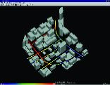
In order to assess the relative calculation speed of Wireless InSite, some comparisons were made with an established propagation prediction tool. Comparison calculations were made for Rosslyn, VA. This is a complex urban area shown in Figure 1 as displayed in 3D by the software package. The calculations were made for 36 buildings of various shapes, multiple transmitter antenna locations and numerous receiver paths. The 2D ray tracing model included with the comparison software was employed and compared with a 2D Wireless InSite calculation. A maximum of five reflections and one diffraction were allowed, and both models used the same building feature descriptions and made calculations for the same number of receiver antenna routes, each about 400 evenly spaced antenna locations along several city blocks. Two different street-level transmitter antenna locations designated A and B were considered, as shown in the diagram as green circles along with the predicted field intensity along the receiver routes for transmitting antenna A.
By monitoring the computer time during the study, the times were recorded and are listed in Table 1.

While the comparison package allows only one route to be calculated at a time, Wireless InSite permits the user to easily make the computation for all the routes simultaneously. When this is done the Wireless InSite run times for all receiver positions are 0:40 for transmitter location A and 0:49 for transmitter location B compared with total times of 23:21 and 25:35, respectively, for the other tool. While these tests were made by a Remcom engineer more familiar with Wireless InSite than with the other package, they indicate a calculation time for Wireless InSite of about 6 percent of that of the other simulator.
How can Wireless InSite be so much faster? First, the computer time required for shooting the rays is reduced by application of computer graphics techniques used for shooting rays at objects to determine highlight and shadow regions for visual rendering. Secondly, Wireless InSite saves and reuses ray path information. For example, a ray may travel from transmitter A to receiver point number 245 by traveling from the transmitter antenna via reflection from building 23 face 1, diffraction from building 17 corner 4, and so on until reaching the receiver location. A ray path from transmitter A to a different receiver location may also include a reflection from building 23, and a diffraction from building 17 corner 4. For other ray-based propagation tools these two receiver locations would require two independent ray shots, while Wireless InSite remembers the ray paths from the first shoot. This is the typical tradeoff between processor time and memory, and the developers of Wireless InSite have developed a procedure to save the ray paths that efficiently uses both memory and CPU cycles to reduce calculation time significantly.
ACCURACY
The calculation engine used in Wireless InSite has been extensively tested and validated by comparison with measured data for a variety of cities. Since Rosslyn, VA is a complex urban area with buildings of different shapes, heights and setbacks, the initial validations of Wireless InSite in Rosslyn had the fortunate effect of encouraging a robust ray tracing method that was not confined to urban areas with rectangular buildings of nearly uniform height. Another effect of the initial Rosslyn validation was the development of a fully three-dimensional (3D) ray model that accommodates arbitrarily oriented building and terrain faces and provides results with full vector fields and, if desired, rays combined with full phase information. This model also allows the user to combine rays with no coherence, partial coherence or full coherence. Partial coherence is also a new development. With this mode rays are sorted to determine if they are interacting with the same building or terrain face. For example, there could be three rays, one that reflects from a building face and two that diffract from two corners of that same face. Wireless InSite will automatically combine these rays coherently. This results in greater accuracy and also removes a theoretical limit on the size of building faces that exists for other ray-tracing propagation tools.
This full 3D version is extremely accurate and general, but relatively slow compared with a two-dimensional (2D) model. An important development was a hybrid 2D/3D model that uses fast 2D ray tracing but then includes vertical building information which allows it to function as a 3D model. In numerous tests the Wireless InSite hybrid Fast 3D model provided nearly identical results with those of the full 3D model, but with much less calculation time. As a result, the program includes four different ray-based propagation models. For urban calculations with low antennas, where over-roof-top propagation is not important, the 2D canyon model is preferred due to its blinding speed. For urban situations where receiver and/or transmitter antennas can be located at elevations such that over-roof-top propagation is important, or when low buildings are involved, the Fast 3D model is used. For situations where full 3D ray tracing is needed, including full vector field with cross-polarization effects, the 3D model is available. For predictions of the effects of uneven terrain on propagation, the terrain model is the correct choice.
In some situations ray-based models are not applicable. This can occur when many blocks of buildings are interposed between transmitter and receiver antennas. For this situation Wireless InSite includes statistical models such as Hata, COST-Hata and COST-Walfisch-Ikegami.
|
|
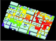

A typical validation exercise for Wireless InSite was performed for Ottawa. The building layout is shown in gray in Figure 2, along with color intensity indicating street coverage predictions. Comparisons with measured data1 are shown in Figure 3. This level of accuracy is representative of the results that can be obtained with Wireless InSite, given accurate building and terrain features data.
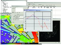
EASE OF USE
Regardless of how fast and accurate a computer model is, it must also be easy to use. The Wireless InSite graphical user interface (GUI) has been in development for over two years. It is designed for Windows operation and its object-oriented organization is clear from the functional layout shown in Figure 4. Wireless InSite is configured to read a variety of urban features data and terrain data formats and to display them. A portion of the city of Denver is shown in Figure 5 after import from a commercially available urban-features CAD file. Building shapes can be edited and new buildings added with the Wireless InSite GUI. Building wall materials can be specified for an entire area, for individual buildings, or even for individual building walls. Receiver and transmitter antenna locations can be added in different ways, and results can be displayed graphically or with color coding. Propagation paths for specific transmitter/receiver antenna pairs are available, along with a wide variety of results including path loss, signal level, delay and delay spread, direction of arrival and many others. Wireless InSite also allows for straightforward organization of study areas so that variations due to antenna placement, frequency, or antenna patterns can be organized and compared.
CONCLUSION
After years of development involving asymptotic electromagnetics and computer graphics technology, a new approach to ray-based urban radio propagation prediction has been implemented. Coupled with a Windows GUI designed specifically for propagation analysis, the result is a powerful software tool for wireless system planners to utilize for accurate prediction of point-to-point and area coverage in urban and rural environments.
Reference
1. J.H. Whitteker, "Measurements of Path Loss at 910 MHz for Proposed Microcell Urban Mobile Systems," IEEE Trans. Veh. Technol., Vol. 37, No. 3, August 1988, pp. 125129.
Remcom Inc.,
State College, PA (814) 861-2543.
Circle No. 302