
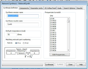
Figure 4 The synthesis definition dialog allows users to specify basic network parameters.
The optimization goals are specified in the wizard using a dedicated set of synthesis measurements, much like optimization goals are normally defined in the design environment platform. Specialized measurements are provided for input noise matching, amplifier output-power matching and inter-stage matching. The optimum reflection coefficients are specified over frequency and can be provided in the form of load-pull data, network parameter-data files or circuit schematics.
Additional practical considerations coded into the synthesizer include the ability to constrain the DC open and short paths in the topology search. For instance, the user can stipulate that the side of the matching circuit next to the device will be DC open, so as not to short the drain or collector. Users can also stipulate minimum and maximum component limits and discrete values to reflect actual available (discrete) vendor parts as well as place constraints on the first and last components in the network. This constraint enables designers to ensure the physical practicality of the synthesized network, such as making sure that a low-impedance transmission line adjacent to a large periphery device is not too wide as to be practical. In addition, the impact of existing bias or feed networks can be incorporated into the synthesis network. The search results are then presented from best to worse (in addressing the performance goals) as each expansion is added.
Interactive User Interface
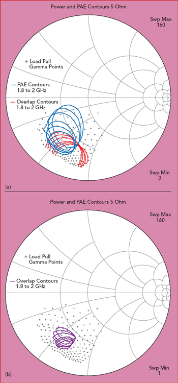
Figure 5 Load-pull contours for power and PAE (a), as well as the intersection of these contours (b), which will provide the impedance targets for the network synthesizer.
It is advantageous to have a network synthesis user interface (UI) that lets designers interactively develop an unlimited number of networks optimized for noise, power or matching networks between amplifier stages or between different components, such as an amplifier and antenna. The optimum reflection coefficients can be specified over frequency and provided in the form of load-pull data, network parameter data files or circuit schematics. Within the synthesis definition tab (see Figure 4), users can specify a default impedance or the impedance of the desired source/load network as well as the desired match frequencies.
The components tab lets users specify the two target networks to be matched from an automatically populated list of project networks (schematics), as well as a set of constraints on the matching network including the number of sections, topology, component type and configuration (series/shunt). Valid topologies are determined by the types of components selected and the value specified for the “maximum number of sections.” Each section is either a series component or a shunt component. The wizard considers topologies having the maximum number of sections, such as N, and with fewer, down to N-3 sections.
Load-Pull Example
The synthesizer is able to interface directly with load-pull data within the software for the instances where designers want to develop matching networks based on nonlinear, load-sensitive performance data. For example, the locus of impedances resulting in power-added efficiency (PAE) and power contours over a given frequency range are plotted on a 5 ohm Smith chart (63 percent PAE and 1 dB power compression point at ~125 W or 51 dBm, five frequencies from 1.8 to 2 GHz), as shown in Figure 5. Alternatively, the designers could plot the overlapping contours, which represent the intersection of the PAE and 1 dB gain compression contours, as shown in Figure 5b.
Instead of providing impedance goals, designers can optionally specify load-pull results directly from within the software. The user simply needs to stipulate the goals, in this case 63 percent PAE and 51 dBm output power, instead of a specific impedance for each frequency point. In this instance, the automation built into the synthesizer tool works from performance goals rather than impedances, which is a much more intuitive approach. The synthesizer provides this capability for sub-bands in support of multi-band matching networks. Goals can be weighted differently, with all the available functionality that is built into the optimizer, such as sloped goals, being supported by the network synthesizer as well.
Additional goals that are not load-pull based can also be added. Figure 6 shows the overlap load-pull contours versus frequency and the initial synthesized-matching network which follows the frequency trajectory of the contours over the desired bandwidth. User-specified target goals can be added to address harmonic terminations to improve linearity and efficiency. Extending the frequency range of the analysis shows that the synthesizer has generated a matching network to provide the desired impedance at the targeted fundamental frequencies as well as the second and third harmonic frequencies.
Post-Synthesis Review
At the end of the synthesizer run, a user-defined number of candidate networks are generated. This provides the designer with an easy and quick method to compare performance results for each network along with a pictogram of the generated layout to provide a visual aid to the designer, as shown in Figure 7.
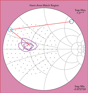
Figure 6 PAE/power overlap load-pull contours at three fundamental frequencies and user-defined additional goals for second and third harmonic terminations.
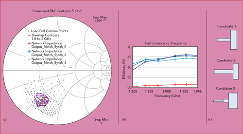
Figure 7 Candidate matching networks and corresponding performance provide users with a method to compare different results and help select the most appropriate circuit.
Conclusion
To help expedite the entire design cycle, a new network synthesis wizard has been added to NI AWR software for the efficient and automated generation of impedance-matching circuits. The synthesis tool generates candidate networks based on user-defined goals, suggested element types to be utilized in the topology search, element constraints/limits and more. The search engine explores possible topologies by expanding the solution up to the maximum number of sections as defined by the user.