
Introduction
In large digital beamforming antennas, dynamic range improvements through the beamforming process of combining signals from distributed waveform generators and receivers is highly desirable. A 10logN dynamic range improvement can be obtained in both noise and spurious performance if the associated error terms are uncorrelated. N in this case is the number of waveform generator or receiver channels. Noise by nature is a very random process and therefore lends itself well to tracking correlated and uncorrelated noise sources. Spurious however are signals which makes it less obvious how to force spurs to be uncorrelated. Therefore, any design method that can force spurious signals to be uncorrelated is valuable to the phased array system architecture.
In this paper we review a previously published technique to force spurious signals to be uncorrelated by offsetting the LO frequencies and digitally compensating for this offset. We then show how the most recent Analog Devices transceiver product, the ADRV9009, has built in features enabling this capability. We then conclude with measured data demonstrating the results of the technique.
Known Spurious Decorrelation Methods
Various methods to force spurious decorrelation in phased arrays have been known for some time. Our first known publication dates back to 20021, where a general method for to ensure receiver spurious are uncorrelated is described. In the approach, signals are first modified in a known way from receiver to receiver. Then the signals become distorted by the receiver’s nonlinear components. At the receiver output, the modifications introduced earlier in the receiver are inverted. The intended signals become coherent or correlated, but the distorted terms are not restored. The modification method implemented in their testing was to set each local oscillator (LO) synthesizer to a different frequency, then correct for the modification by digitally tuning numerically controlled oscillators (NCO) in the digital processing. Several other methods have been published also.2-3
 Years later, with the advanced integration of full transceiver subsystems in single monolithic silicon, embedded programmable features in the transceiver products enable the spurious decorrelation method described in.1
Transceiver Features Enabling Spurious Decorrelation
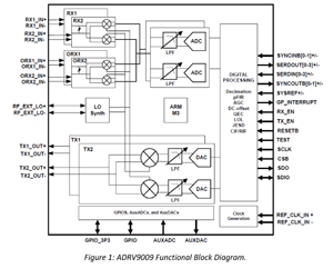
A functional block diagram of the Analog Devices transceiver ADRV9009 is shown in Figure 1.
Each waveform generator or receiver is implemented with a direct conversion architecture. See reference5 for further description of direct conversion architectures. The LO frequencies can be programmed independently on each IC. The digital processing section includes digital up-/down-conversion with NCOs that can also be programmed independently across ICs. See reference6 for further description of digital down conversion.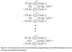
Next we will demonstrate a method to force spurious decorrelation across multiple transceivers. First, the LOs are offset in frequency by programming the on-board phase locked loops (PLL). Then the NCO frequencies are set to digitally compensate for the applied LO frequency offset. By adjusting both features inside the transceiver IC, the digital data to and from the transceivers does not have to be offset in frequency and the entire frequency translation and spurious decorrelation is built into the transceiver IC.
 A representative block diagram for an array of waveform generators is shown in Figure 2. In our description we will describe the method and show data for waveform generators, but the method is equally applicable to an array of receivers.
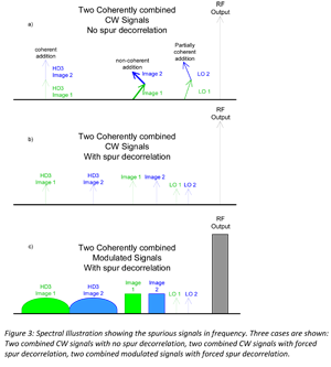
To illustrate the concept in frequency, an example with two transmit signals from a direct conversion architecture is shown in Figure 3. These cases are shown where the RF is on the high side of the LO. In a direct conversion architecture the image frequency and third-harmonic appear on the opposite side of the LO and are shown below the LO frequency. When the LO frequencies are set the same frequency across channels, the spurious frequencies are also at the same frequencies as shown in Figure 3a. Figure 3b illustrates a case where LO2 is set at a higher frequency than LO1. The digital NCOs are equally offset such that the RF signal achieves coherent gain. The images and third harmonic distortion products are at different frequencies and thus uncorrelated. Figure 3c illustrates the same configuration as Figure 3b but adds modulation to the RF carrier.