
Coplanar strip transmission lines (CPS) are widely used, for example, whenever balanced lines are required to feed printed circuit board (PCB) antennas or in balanced mixers, or as interconnecting lines in high speed digital circuits. In such circuits, differential transmitters and receivers are employed, especially when electronic devices have to operate in very noisy environments. In such cases CPS assume great importance. The original CPS geometry and associated design equations do not take into account the presence of a bottom ground conductor, which is often present. This article describes the simple development of closed form equations for characteristic impedance and effective dielectric constant for the conductor-backed asymmetric coplanar strip (CBACPS) using quasi-static analysis, while also considering the effect of a top ground cover. These equations also include the case of the conductor-backed symmetric coplanar strip (CBSCPS), as well as the symmetric or asymmetric coplanar strip not conductor-backed, and are well suited to be implemented in CAD simulation tools.
This work represents an extension of the conductor-backed coplanar strip (CBCPS) analysis presented in the May 2000 issue of Microwave Journal,1 removing the constraint of equal width used in the CBCPS analysis. In general, the presence of a bottom ground plane is a practical difference with respect to the original CPS transmission line where two conductors strips of equal width w are placed near them at a distance s, positioned above a dielectric plane of theoretically infinite thickness h. This structure shall be called a symmetric CPS (SCPS). C.P. Wen first studied2 this transmission line with a conformal mapping technique3 , as the complementary case of the symmetric coplanar waveguide (SCPW), with the further assumption of conductors with negligible thickness t.
Another practical difference with the original SCPS is that the substrate is, in practice, of finite dimension h. This case was first studied by J.B. Knorr and K.D. Kuchler4 with a full-wave analysis, and then by others with quasi-static5,6 or full-wave methods.7 Closed form expressions for SCPS characteristic impedance and effective dielectric constant for this case have been given by I.J. Bahl, et al.8
Another difference is the inevitable conductor thickness t. The resulting effect can be evaluated as H.A. Wheeler9 originally did for the microstrip case, and subsequently applied to CPS by K.C. Gupta, et al.8 Losses have been examined by K.C. Gupta et al.,8 and unequal widths CPS have been studied by I. Kneppo and J. Gotzman,10 and by R.K. Hoffmann.11 High speed pulse propagation in CPS has also been investigated,1214 verifying the capability of this transmission line configuration for this purpose.
ANALYSIS OF CONDUCTOR-BACKED ASYMMETRIC COPLANAR STRIP
The geometrical structure to be analyzed is shown in Figure 1. Two conductor strips of unequal widths w1 and w2 are placed close together at a distance s, positioned on the top side of a dielectric plane of thickness h, with the other side connected to ground. It is assumed that a pure TEM mode will propagate in this transmission line only if a homogeneous dielectric media surrounds the strips. Conductor thickness t is supposed to be infinitesimal. This structure will be studied by performing the theoretical analysis once for the top half space and once for the bottom dielectric space. This procedure is suitable when a conformal transformation method (CTM) is employed for analysis, as in this case.

Under the TEM propagation mode it is assumed, from electric field strength line symmetry, that to simplify the study an ideal electric plane (IEP) can be placed at the middle of the spacing s and orthogonal to the ground plane. Due to this symmetry, the transverse section of the configuration is composed of four quadrants. Then, to evaluate the transmission line equivalent capacitance, only one quadrant of the top space and one quadrant of bottom space is studied.
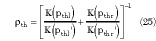
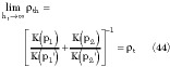
At present, whenever possible, the shape factor variables pi will be used, defined as
This shape factor is widely used for the analysis of other coplanar lines such as CPS and CPW.
Bottom Part Analysis
The starting geometry is shown in Figure 2, which will be transformed in the structure indicated in part c of the diagram. However, note that the capacitance that will be evaluated is only relative to the BR part. Once the same procedure is repeated for the BL part, the entire capacitance for the bottom part of the CBACPS will be the series of the previous two capacitances. The transformation from part a to part c is performed through two Schwarz-Christoffel transformations. The same procedure must be repeated for the BL part.

The analytical transformations involved in such a procedure were previously reported in detail1 , and consequently only the final results will be reported here. The full bottom capacitance Cb of the CBACPS is
Cb = *0 *rb *b (2)
where
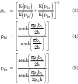
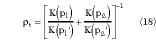
The generic ratio K(q)/K(q') is the ratio of the complete elliptic integrals of first kind,15 evaluated by W. Hilbert16 and given by
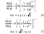
with a maximum error of 3 ppm with respect to the tabulated exact values of K(q) and K(q'). The primed variables are the complementary parameters defined as (q')2 = 1 q2 .
Top Part Analysis
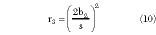
To evaluate the total capacitance C per unit length of the CBACPS structure, the capacitance Ct of the unlimited top part of CPS also must be evaluated. This situation is shown in Figure 3. The transformation between the top right part TR and part b of the diagram is performed through a Schwarz-Christoffel transformation using the equation z = LI3 + M, where L and M are constants and I3 is


Solving the previous simple integral and applying the relationships z = 0  r1 = 0 and z2 = s/2 r2 = 1, the desired transformation becomes

from which
Then, the geometry in the R plane is mapped to that indicated in part c, through another Schwarz-Christoffel transformation t = NI4 + P where N and P are constants and I4 is
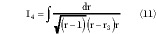
that with the variable substitution
r = (1 r3 )δ2 1 (12)
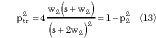
can be transformed in the elliptic integral of the first kind F (δ,ptr ), with parameter ptr given by the positive square root of the expression
Thus, the final transforming equation can be written as
t = QF(δ,ptr ) + R (14)
where Q and R are constants. Applying the relationships t1 = 1 r1 = 0, t2 = 1 + jd r = r2  1 and t3 = jd r = r3 , the desired value of d becomes

The resulting capacitance per unit length of the structure is therefore Ctr = ε0 εrt K(ptr )/K(ptr ').
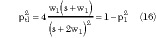
Now the same procedure must be repeated for the TL part, reported in part d. Performing this, an expression for d is obtained similar to Equation 5, but with parameter obtained by the positive square root of the expression
and, consequently the resulting capacitance per unit length of the TL part is Ctl = ε0 εr K(ptl )/K(ptl '). Therefore, full top capacitance of part a is
Ct = ε0 εrt  t (17)
where
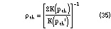
Full Analysis
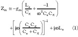
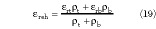
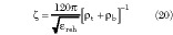
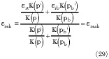
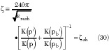
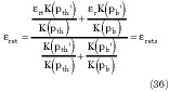
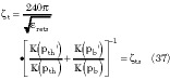
Combining the previous results, the effective relative dielectric constant εreh and characteristic impedance  for the CBACPS are
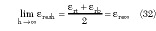
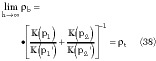
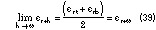
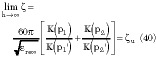
For the limit values when h 0 note that
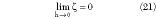

Equation 21 is physical, since when h = 0 the two conductors are short-circuited and the characteristic impedance of the line is zero, while Equation 22 is analytical but not physical. In fact, if h = 0 the substrate does not exist and the result of Equation 22 must be interpreted that when h = 0 the electromagnetic field tends to be completely concentrated in the substrate. Again, it has no physical counterpart, since for h = 0 no transmission line exists and = 0.
ANALYSIS OF TOP-SHIELDED CBACPS
The top-shielded CBACPS (TSCBACPS) geometrical structure is composed by adding a top ground conductor over the CBACPS two conductors layer, at a distance ht . The study of this structure can be performed similar to the previous procedure. Thus, the effective relative dielectric constant *ret and the characteristic impedance t are

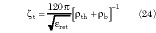
where *th is defined as
and the parameters pthx , with x = r,l, are obtained by replacing h and ht in Equations 4 and 5.
THEORY APPLICATIONS TO OTHER COPLANAR STRIP TRANSMISSION LINES
The results for the original SCPS, both conductor-backed or not, can simply be obtained from the developed theory. In both cases w1 * w2 = w must be set and consequently p1 * p2 = s/(s+2w) = p. Design equations for unbacked asymmetric CPS (ACPS) can also be obtained.
The equation for the bottom part of the conductor-backed symmetric coplanar strips (CBSCPS) is
and Equation 4 becomes

The top part of the CBSCPS is

and the full analysis becomes1
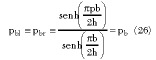
For the case of the unbacked symmetric coplanar strip (SCPS) from Equation 26

Consequently, the ratio of the complete elliptic integrals of first kind in Equations 29 and 30 evaluated with pb or p have the same value for h  , therefore
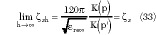
Equations 32 and 33 are well-known expressions for the unbacked SCPS2,8
A similar analysis for TSCBSCPS produces, for the bottom part, Equations 26 and 27, and for the top part
and Equation 25 becomes
Full Analysis
The effective relative dielectric constant and characteristic impedance, given in Equations 23 and 24, respectively, become1
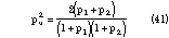
For the unbacked ACPS it is observed that for the bottom part
Note how the previous equation is the extension to the asymmetric and conductor-backed case of Equation 27. The same results of the CBACPS apply for the top part. Using the result in Equation 38 for the full analysis gives
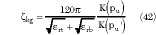
Note how the previous equation is the generalization of Equation 33 that includes the asymmetric case. Equation 40 is different from the already presented expressions for ACPS characteristic impedance. Until today two expressions existed, both obtained with quasi-static methods like in the actual case but with parameters pu according to
One expression has been given by Kneppo-Gotzmann,12 resulting in
and the other by Hoffmann, resulting in13
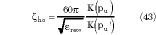
For the ACPS case, the present theory gives a percentage difference for with respect to ho , which is below 7% for any practical value of p12 , (that is, p12 ≤ 10) and independent from εrb . kg gives instead a percentage difference which is directly proportional to εrb but independent of p12 and for the alumina case the percentage difference is near 13%.
RELATIONS BETWEEN CBACPS AND TSCBACPS
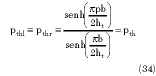
It is interesting to verify how within the limit of operations for ht the theory developed for TSCBACPS gives the same results as for the CBACPS. In fact, note that

as it should be. Once the TSCBACPS theory with limited operations is transformed to ACPSG theory, all the limits applicable and shown previously are also applicable now. In particular, note that

as it should be. Of course, the other CPS transmission lines previously discussed can also be obtained with limited operations starting from TSCBACPS.
CBACPS AND TSCBACPS CHARACTERISTIC CURVES
In the following graphs p1 is used as the sweeping variable, with p12 = p1 /p2 and h/b1 as parameters, and the top side dielectric constant εrt will be set equal to 1. For frequencies in the 2 to 20 GHz band typical values of p1 , for i = 1,2, are within the 0.1 to 0.4 interval, while for lower frequencies values outside this range are possible.
Since all p parameters are bounded in the 0 to 1 range, according to their definition, expressing pb1 and pbr as function of p12 it is possible to show that the condition p12 ≥ 1 must be verified, that is, p1 ≥ p2 . However, this condition is only an analytical constraint, since the EM characteristics of the structure are independent of which conductor has width w1 or w2 . Thus, if in the following graphs p12 ≥ 1 is used, from the EM point of view the graphs are also valid for p2 > p1 only interchanging subscripts 1 and 2 in the graphs. Parameter p12 is useful to understand the ACPS geometry, by simply knowing its value. In fact, p12 = 1 means a symmetric CPS (SCPS) and p12 > 1 means an asymetric CPS (ACPS).
The effect of h variations on εre vs. p1 are shown in Figure 4, for alumina with εr = 10. Here the percentage difference Δε(p1 ,p12 ,h/b1 ,εrb ,εrt ) between εre and εre vs. p1 is defined as
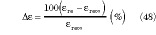
Note that if h/b1 ≥ 2 the difference is below 10%.
To simply evaluate the effect of h on the impedance an interesting function is the percentage difference Δ between and u vs. p1 , defined as
and shown in Figure 5. Note that the percentage difference increases with asymmetry and Δ 0 for h . It is important to observe that small values of p1 mean small values for s and/or large values of w1 . However, this last condition is not advisable in practice, since a large value of w causes the possible growth of unwanted modes. The existence of these modes in CBSCPS can be rigorously justified with full-wave methods,17 and is still under investigation.18
The percentage difference Δ t between t and u vs. p1 , defined as
is shown in Figure 6. Note how the difference is strongly dependent on the asymmetry.
Of course, curves for CBSCPS similar to those presented here are obtained by drawing the respective functions with the parameter p12 = 1.
CONCLUSION
A quasi-static approach has been used to study the CBACPS. Formulas for characteristic impedance and effective dielectric constant have been given, which can also be used for symmetrical and unbacked CPS. These formulas are well suited to be implemented in CAD simulation tools and to help in the design of many microwave devices employing balanced transmission lines. The results of the analysis show that the effect of a bottom ground conductor decreases the characteristic impedance of the ACPS. A top-shielded CBACPS also has been studied, and analysis formulas have also been given for this transmission line. *
References
1. F. Di Paolo, "An Analysis of Enclosed Coplanar Strips," Microwave Journal, Vol. 43, No. 5, May 2000, pp. 314326.
2. C.P. Wen, "Coplanar Waveguide: A Surface Strip Transmission Line for Nonreciprocal Gyromagnetic Device Application," IEEE Transactions on Microwave Theory and Techniques, December 1969, pp. 10871090.
3. F. Di Paolo, "Networks and Devices Using Planar Transmission Lines," CRC Press, 2000.
4. J.B. Knorr and K.D. Kuchler, "Analysis of Coupled Slots and Coplanar Strips on Dielectric Substrate," IEEE Trans. on MTT, July 1975, pp. 541548.
5. V.F. Hanna, "Finite Boundary Corrections to Coplanar Stripline Analysis," Electronics Letters, July 1980, pp. 604606.
6. G. Ghione and C. Naldi, "Analytical Formulas for Coplanar Lines in Hybrid and Monolithic MICs," Electronics Letters, February 1984, pp. 179181.
7. S.G. Pintzos, "Full-wave Spectral Domain Analysis of Coplanar Strips," IEEE Transactions on Microwave Theory and Techniques, February 1991, pp. 239246.
8. K.C. Gupta, R. Garg and I.J. Bahl, "Microstrip Lines and Slotlines," Artech House, 1979, p. 276.
9. H.A. Wheeler, "Transmission Line Properties of a Strip on a Dielectric Sheet on a Plane," IEEE Transactions on Microwave Theory and Techniques, August 1977,pp. 631647.
10. I.Kneppo and J.Gotzman, "Basic Parameters of Nonsymmetrical Coplanar Line," IEEE Transactions on Microwave Theory and Techniques, August 1977, p. 718.
11. R.K. Hoffmann, "Handbook of Microwave Integrated Circuits," Artech House, 1987, p. 370.
12. U.D. Keil, D.R. Dykaar, A.F.J. Levi, R.F. Kopf, L.N. Pfeiffer, S.B. Darack and K.W. West, "High Speed Coplanar Transmission Lines," IEEE JQE, October 1992, pp. 23332342.
13. M.Y. Frankel, R.H. Voelker and J.N. Hilfiker, "Coplanar Transmission Lines on Thin Substrates for High Speed Low Loss Propagation," IEEE Transactions on Microwave Theory and Techniques, March 1994, pp. 396402.
14. H. Cheng, J.F. Whitaker, T.M. Weller and L.P.B. Katehi, "Terahertz Bandwidth Pulse Propagation on a Coplanar Stripline Fabricated on a Thin Membrane," MGWL, March 1994, pp. 8991.
15. M. Abramowitz and I.A. Stegun, "Handbook of Mathematical Functions," Dover, 1970, p. 589.
16. W. Hilberg, "From Approximations to Exact Relations for Characteristic Impedances," IEEE Transactions on Microwave Theory and Techniques, May 1969, pp. 259265.
17. M. Tsuji, H. Shigesawa and A.A. Oliner, "Simultaneous Propagation of Both and Leaky Dominant Modes on Conductor-backed Coplanar Strips," IEEE MTT Symposium, 1993, pp. 12951298.
18. A.B. Yakovlev and G.W. Hanson, "On the Nature of Critical Points in Leakage Regimes of Conductor-backed Coplanar Strip Line," IEEE Transactions on Microwave Theory and Techniques, January 1997, pp. 8794.
Franco Di Paolo received his doctorate degree in electronic engineering in 1984 from Università degli studi di Roma 'La Sapienza.' He started working at Ericsson in Rome in 1986 as a RF hardware designer of amplifiers, modulators, oscillators and PLL's for high bit transfer rate laser transmitters and receivers. He joined Elettronica SpA in Rome in 1992 as a microwave and RF hardware designer in wide bandwidth microwave circuits and MMICs. Currently, he is a RF and microwave research engineer in TELIT SpA's Satellite Division in Rome in applied electromagnetism and RF/microwave design. Di Paolo is the author of the book "Networks and Devices Using Planar Transmission Lines," CRC Press, 2000. The author can be reached via email at franco.di.paolo@ntt.it.