
A new architecture for RF and microwave measurement has recently been introduced. The first instrument based on this architecture is called the modulated vector network analyzer (MVNA™). The MVNA shares some similarities with traditional vector network analyzers (VNA), which use sinusoidal stimuli to measure scattering parameters. The MVNA also has the ability to measure S-parameters, but can do so using modulated waveforms.
The concept of modulated S-parameters is new to the test and measurement world. The traditional VNA could not use real world signals, that is stimulus matching the end use of the device under test. Because of this drawback there has been some confusion about what modulated S-parameters mean. This article introduces the concept of modulated S-parameters. However, before discussing them, it is best to start with traditional (sinusoidal) S-parameters.
SINUSOIDAL VECTOR NETWORK ANALYSIS
Figure 1 shows the four S-parameters for a two port device. The S-parameters are transfer functions which generally have different complex values at different frequencies. These functions of frequency describe how the device modifies input waveforms (a1 and a2 ) and produces output waveforms (b1 and b2 ).

Mathematically, the four S-parameters are defined as
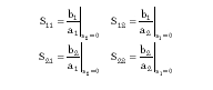
Thus, S11 is the ratio of b1 to a1 when a2 is zero, and similarly for the other S-parameters.
In order to account for the non-ideal properties of the measurement instrument and various cables and fixtures connecting the instrument to the device, a model accounting for these errors is introduced. Figure 2 shows a six-term forward error model for a VNA. The reverse error model is similar, but with slightly different names for the error terms. In this model the measured waveforms have an M subscript, while the actual waveforms at the device have an A subscript. The S-parameters of the device are also denoted with an A subscript to distinguish them from the measured S-parameters. The terms beginning with an E are the error terms, which are used to model the non-ideal properties.

Through a process called calibration, the complex values of the error terms as functions of frequency are determined. The various terms in the error model are assumed not to vary over time or power level. They are assumed to model a system, which is linear. If the instrument, cables or fixtures are nonlinear then the error model will not be a good representation.
Figure 3 shows the flow of measuring and computing S-parameters. The arrows represent physical or mathematical operations while the boxes represent results.

The VNA applies a sinusoid of a known frequency at point a1M . Measurements are made at points b1M and b2M . Measurements made in this manner are called forward measurements. A sinusoid of the same frequency is then applied at point a2M and measurements made at b1M and b2M . Measurements made in this manner are called reverse measurements.
These forward and reverse measurements are then combined mathematically in a process called ratioing to produce measured S-parameters (for example, S11M ).
The effects of the various error terms in the six-term forward error model can then be removed by a process called vector error correction. The results of vector error correction are the actual S-parameters of the device (for example, S11A ).
Once the S-parameters have been determined for one frequency, the frequency can be changed and the measurement and mathematical process repeated. The end result of a VNA measurement of a two port device is the four S-parameters with the effects of the instrument and connections removed. These four transfer functions are complex functions of frequency.
MODULATED VECTOR NETWORK ANALYSIS
An MVNA operates similarly to a VNA in that it applies a stimulus at point a1M in the forward error model. However, in this case the stimulus is not a sinusoid of a single frequency, but rather a modulated waveform with a continuum of energy spread around a carrier frequency. In order to produce this modulated signal, the sinusoidal source of the VNA is replaced by a modulated source. In the case of the MVNA, the source most frequently used is a synthesized RF signal generator with the I/Q modulator driven by two high speed arbitrary waveform generators; however, any modulated or unmodulated RF signal can be applied.
On the measurement side, wideband receivers replace the narrowband receivers of a VNA. Each receiver in the MVNA is a high speed transient digitizer with 15 MHz of usable bandwidth. Where the VNA must move from frequency to frequency making measurements at each, the MVNA can capture up to 15 MHz of frequency content at a time.
Thus, modulated S-parameters are computed very similarly to sinusoidal S-parameters. The primary difference being the MVNA's ability to compute S-parameters at multiple frequencies based on a single acquisition rather than repetitive, stepped frequency measurements.
THE USEFULNESS OF MODULATED S-PARAMETERS
The ability to measure S-parameters under modulated stimuli can be quite valuable, particularly for devices that behave differently under sinusoidal or modulated stimuli. Amplifiers operating near their compression point are a particularly good application of the MVNA because the gain S21 and input match S11 can be functions of the excitation type. One classic problem is to tune the input match and gain of an amplifier using a sinusoidal VNA, and then use the device to amplify a modulated signal. The careful tuning of the input matching accomplished using the sinusoid is invalidated because the match is different when using the modulated signal. By contrast, the MVNA allows tuning of the input match and gain of the amplifier using the waveform of interest.
For devices with signal characteristics varying with power or time, the MVNA offers a clean means of determining the S-parameters using the waveform of interest. Devices which do not benefit from measurements on an MVNA are passive devices or devices operating linearly. Thus, cables, connectors, filters and attenuators do not exhibit different S-parameters when measured with sinusoids or modulated waveforms. This fact is somewhat comforting, actually, for it shows that modulated S-parameters are the same as sinusoidal S-parameters in cases where the excitation source should not matter.
CONCLUSION
The ability to measure S-parameters under modulated stimuli can be quite valuable in analyzing the behavior of active devices, particularly those for which high linearity is a desirable performance characteristic. The MVNA allows accurate measurement of device characteristics under real world signal conditions. That is, the test stimulus matches the intended use of the device. The process of calculating modulated S-parameters is similar to the traditional method except for the data acquisition receiver bandwidth. *
 Don Metzger is the founder of the Modulation Instruments division of Credence Systems Inc., and serves as the division's CTO. He holds a PhD in electrical engineering from the University of Colorado with specialization in electromagnetic fields. In the past he has been a consultant to Anritsu in the areas of calibration and digital signal processing. He is the inventor of Anrtisu's Auto Cal line of calibration units for vector network analyzers and was the lead developer of the time domain processing used in Anritsu's network analyzers.