
Shielding Formulas for Near Fields
R.C. Hansen
Consulting Engineer
Tarzana, CA
This article reviews extremely low frequency (ELF) formulas for magnetic shielding effectiveness. In particular, the simple three-term Schelkunoff formula is accurate at all frequencies if the proper near-field, or far-field, wave impedance is used.
Electromagnetic shielding of rooms or equipment through the use of metal walls or sheets has been important for many decades, and is now even more necessary with the burgeoning number of RF transmitters of all types, both inside and outside of buildings. Many devices such as electronic typewriters and computers emit ELF radiation. For plane wave sources there are well-known simple formulas for transmission through a metal sheet (or through a multiple-layer wall) using A-B-C-D or equivalent chain matrices. Often the frequencies of interest are sufficiently low that the metal wall is in the near field of a source or test antenna. For these cases, the shielding effectiveness (SE) (the ratio of the incident field to the exit field) may be significantly different than for the plane wave case. This article reviews formulas for the near-field case.
SCHELKUNOFF SHIELDING THEORY
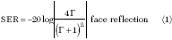
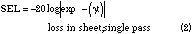
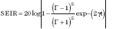
Cylindrical and spherical shields were investigated by Schelkunoff1 many decades ago. He showed that SE can be written as three terms (in decibels) representing the primary reflection at the air-metal interface, the attenuation (diffusion loss) for a single pass through the metal wall and a correction term to account for the internal reflections and additional attenuation in the material. These formulas have been applied to plane sheets and used by many workers. The terms, of course, result from the exact formula for transmission of a plane wave through a sheet of arbitrary material.2,3 To recapitulate, the three terms are
? additional internal attenuation
and reflection loss
The SE, in decibels, is the sum
SE = SER + SEL + SEIR
The reflection coefficient G is

The sheet thickness is t and its impedance and propagation constant are Zsheet and  . The critical contributions of Schelkunoff were to formulate transmission through a wall -- long before the Radiation Laboratory work -- and to recognize that near-field effects could be subsumed into the external wave impedance Zwave .
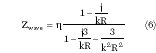
At low frequencies most antennas (and inadvertent radiators) are loops. The small loop near-field wave impedance is usually computed as the ratio of the well-known near-field components Ef /H . Whitehouse4 demonstrated that the correct wave impedance uses the ratio of transverse fields, where Htrans = Hr sin + H cos . (Transverse fields apply when the plane of the loop is parallel to the wall; other loop orientations will have a different wave impedance.) This relationship results in a wave impedance of
where
|
R |
= |
distance from the source loop |
|
|
|
to the receiving loop |
|
k |
= |
2p / |
|
|
= |
120 p |

Whitehouse modified Equation 6 to include the effect of loop radius, replacing R with√R2 + a2 where a is the loop radius. As will be shown, use of this modified near-field wave impedance produces very good results. The wall must be infinitely large or, if part of a shielded room, sufficiently large to encompass most of the incident field.
LOOP-TO-LOOP CALCULATIONS
In a classic paper, Moser5 obtained the SE of a metal wall when the source antenna was an electrically small loop, and when the wall was in its near field. The loop magnetic field was expanded into an integral of plane waves; each plane wave component was propagated through the wall. This work was recently extended to include an electrically small receiving loop, again in the near-field regime.6 This formulation matches the experimental setup,5 which was loop-to-loop, and is rigorous as long as the loops are sufficiently small to maintain constant current.
THEORIES vs. EXPERIMENTS
Carefully measured data on the SE of metal sheets are sparse; Moser's5 data are used here. He measured three materials -- copper, aluminum and steel -- each roughly 1/16- and 1/8-inch thick. Both transmit and receive loops were 7 cm in diameter. The power source was a 200 W McIntosh amplifier with a low impedance, providing a roughly constant voltage on the source loop. The receive loop open circuit voltage was measured both with the sheet present and absent. For a fixed distance between loops, the SE was found to be roughly independent of the distance of the sheet from the transmit loop (as predicted by the plane wave spectrum theory). As long as the sheet is large enough to encompass most of the field, the near-field effect is from one loop to the other; the loop-to-loop distance affects the wave impedance.
Using the correct wave impedance, the exact loop-to-loop calculations (and the Schelkunoff formulation results) are compared here with the Moser measured data. Figure 1 shows data for 1/16-inch copper sheet with loop-to-loop spacing of 3 cm. It is apparent that the agreement between numerical results from the exact theory and measurements is very good. The Schelkunoff formulation results are very close to the exact results. Figure 2 shows data for a steel sheet with conductivity of 9.86E6 S/m and a permeability of 112. A loop-to-loop spacing of 3 cm was used. Again, agreement between theoretical results and the measurements is very good. For the copper sheet, the thickness equals one skin depth at 1.733 kHz; for the iron sheet this condition occurs just below 0.1 kHz. For larger loop-to-loop distances, the Schelkunoff results are an excellent match to the exact results. To illustrate the contribution of the individual terms in the Schelkunoff formula, the copper sheet at 2 kHz was used as an example. The face reflection is 15.6 dB, skin depth loss is 9.3 dB and internal reflection loss is 0.6 dB, for a total of 25.5 dB.


CONCLUSION
Schelkunoff's formulas are excellent for calculating near-field SE of metal sheets, provided the transverse near-field wave impedance is used. The formulas are also excellent for far-field (plane wave) calculations, where the free space wave impedance is used.
References
1.? S.A. Schelkunoff, Electromagnetic Waves , Van Nostrand, 1943, Section 8.18.
2.? W.M. Cady, M.B. Karelitz and L.A. Turner, Radar Scanners and Radomes , Vol. 26, Rad. Lab. Series, McGraw-Hill, 1948, Section 12.5.
3. T.E. Tice (editor), Techniques for Airborne Radome Design , Technical Report AFAL-TR-66-391, Vol. 1, December 1966, Chapter 2, AD-811 355.
4. A.C.D. Whitehouse, "Screening: New Wave Impedance for the Transmission-line Analogy," Proc. IEE , Vol. 116, July 1969, pp. 11591164.
5. J.R. Moser, "Low-frequency Shielding of a Circular Loop Electromagnetic Field Source," Trans. IEEE , Vol. EMC-9, March 1967, pp. 618.
6. R.C. Hansen and J.R. Moser, "Loop-shield-loop Shielding Effectiveness," Trans. IEEE , Vol. EMC-41, May 1999, pp. 144146.