
HYBRID BEAMFORMING
In a hybrid beamforming system, both the precoding weights and the combining weights are combinations of baseband digital weights and RF band analog weights. This type of architecture is shown in Figure 6.
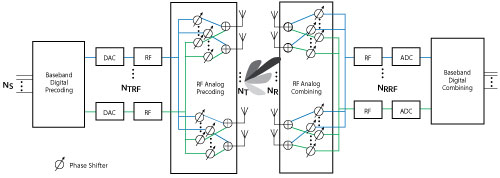
Figure 6 Hybrid beamforming architecture.
For this discussion, assume a set of larger arrays: The transmitter consists of a 64-element square array with four RF chains, and the receiver is based on a 16-element square array with four RF chains. Each antenna is connected to all RF chains, which means that each antenna is connected to four phase shifters. This type of array can be modeled by partitioning the array aperture into four completely connected subarrays. To maximize the spectral efficiency in the system, each RF chain can be used to send an independent data stream. In this case, the system supports up to four streams.
A scattering environment with six scattering clusters randomly distributed in space is used to define the channel. Within each cluster, there are eight closely located scatterers, for a total of 48 scatterers. The path gain for each scatterer is obtained from a complex circular symmetric Gaussian distribution.
As described earlier, in a spatial multiplexing system with all-digital beamforming, the signal is modulated by a set of precoding weights, propagated through the channel and recovered by a set of combining weights. Mathematically, this process can be described by Y = (X*F*H+N)*W where
- Ns is the number of data streams.
- Nt is the number of transmit elements.
- Nr is the number of receive elements.
- Nrf is the number of RF channels.
- X is an Ns-column matrix whose columns are data streams.
- F is an Ns × Nt matrix representing the precoding weights.
- H is the channel representation.
- W is an Nr × Ns matrix representing the combining weights.
- N is an Nr-column matrix whose columns are the receiver noise at each element.
- Y is an Ns-column matrix whose columns are recovered data streams.
Since the goal of the system is to achieve better spectral efficiency, obtaining the precoding and combining weights can be considered an optimization problem in which the optimal precoding and combining weights make the product of F*H*W a diagonal matrix, so each data stream can be recovered independently.
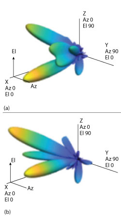
Figure 7 Transmit patterns for all-digital (a) and hybrid (b) cases.
In a hybrid beamforming system, the signal flow is similar. Both the precoding weights and the combining weights are combinations of baseband digital weights and RF band analog weights. The baseband digital weights convert the incoming data streams to input signals at each RF chain, and the analog weights then convert the signal at each RF chain to the signal radiated or collected at each antenna element. Note that the analog weights can only contain phase shifts. Mathematically, it can be written as F = Fbb*Frf and W = Wbb*Wrf, where
- Fbb is an Ns × NtRF matrix.
- Frf is an NtRF × Nt matrix.
- Wbb is an NrRF × Ns matrix.
- Wrf is an Nr × NrRF matrix.
Since both Frf and Wrf can only be used to modify the signal phase, there are extra constraints on the optimization process to identify the optimal precoding and combining weights. Ideally, the resulting combination of Fbb*Frf and Wrf*Wbb are close approximations of F and W that are obtained without those constraints. Unfortunately, optimizing all four matrix variables simultaneously is quite difficult. Many algorithms exist that arrive at suboptimal weights with a reasonable computational load. This example uses an approach that decouples the optimizations for the precoding and combining weights. It first uses the orthogonal matching pursuit algorithm to derive the precoding weights. The hybrid weights can be computed as
[Fbb, Frf] = helperHybridPrecodingWeights(H, NtRF, Ns, At);
Once the precoding weights are computed, the result is used to obtain the corresponding combining weights. Assuming the channel is known, the unconstrained optimal precoding weights can be obtained by diagonalizing the channel matrix and extracting the first NtRF dominating modes.
The transmit beam pattern for both cases is shown in Figure 7. The response patterns show that even in a multipath environment, the number of dominant directions is limited. The beam pattern using the hybrid weights is similar to the beam pattern obtained using the optimal weights, especially for the dominant beams. This result means that the data streams can be successfully transmitted through those beams using hybrid weights.
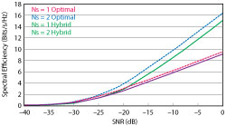
Figure 8 Spectral efficiency of all-digital and hybrid systems.
One of the system-level performance metrics of a 5G system is the spectral efficiency. Figure 8 compares the spectral efficiency achieved using the optimal weights with the proposed hybrid beamforming weights. The simulation assumes one or two data streams. The transmit antenna array is assumed to be at a base station, with a focused beam coverage of 60 degrees in azimuth and 20 degrees in elevation. The signal can arrive at the receive array from any direction. The resulting spectral efficiency curve is obtained from 50 Monte Carlo trials for each SNR. Figure 8 shows that the spectral efficiency improves significantly by increasing the number of data streams. In addition, hybrid beamforming can perform close to what optimal weights can offer and uses less hardware.
SUMMARY
MIMO systems enable spatial multiplexing techniques that can be used to improve data throughput. This improvement is achieved by applying a set of precoding and combining weights derived from the channel matrix. Because 5G systems require large antenna arrays, applying digital weights on each antenna element is not always practical. Hybrid beamforming can be applied in a mixed RF and digital beamforming system to lower system costs. System modeling techniques can be used to explore system tradeoffs before any hardware is built, which can prevent costly errors and project delays.