
Finite Element Analysis of RF Couplers With Sliced Coaxial Cable
N. Benahmed and M. Feham
University of Tlemcen, Department of Electronic
Tlemcen, Algeria
This article presents the analysis of two coupled lines with sliced coaxial cable, based on a numerical resolution of the Laplace's equation by the finite element method (FEM). This technique is adapted to study the complex configuration of the line's system, which does not have a simple analytical solution. The modelling of this structure consists in analyzing the even- and odd-mode characteristic impedances (Zoe , Zoo ), the coupling coefficient k, and the matrices [L], [C], [R] and [G]. The results of an RF coupler design are presented as an application. The numerical model developed remains valid to all configurations of structures that propagate the fundamental TEM-mode.
The analytical characterization of coupling between two coupled lines with sliced coaxial cable is a difficult task. Numerical methods are appropriate to solve this problem. In order to reach this objective in a numerical way, it is necessary to evaluate, first the characteristic impedances of the even and odd modes and then the primary parameters [L], [C], [R] and [G] of the structure.
In this work, the numerical characterization of the coupling coefficient and the primary parameters of two coupled lines with sliced coaxial cable by using the finite element method are of interest.
Using this technique, the influence of the electrical and geometrical parameters of the analyzed structure is obtained. Finally, the design of an RF coupler is described.
COUPLED LINES WITH SLICED COAXIAL CABLE
Recently, a directional coupler has been analyzed and tested with a coupled line composed of two shaped cut coaxial cables.1 This kind of coupler has excellent performance in terms of high directivity, very low SWR, good isolation, excellent electromagnetic interference (EMI) shielding, high power handling capability, extremely low cost due to the use of commercial semi-rigid coaxial cables and elimination of mechanical housing.2
The electrical properties of the coupler with a TEM-mode coupled line can be described in terms of even (Zoe ) and odd (Zoo ) mode impedances. Various numerical techniques can be used to determine the accurate characteristic impedances of the TEM coupled line.3
RESULTS OF THE REFERENCE
An et al3 presented the formulas for even- and odd-mode characteristic impedances of a coupled line with a sliced coaxial cable. The cross-section of a coupled line with sliced coaxial cable is shown in Figure 1 .
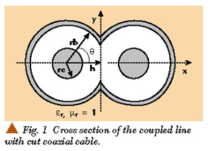
The cable is assumed to be lossless with an inner conductor of radius rc and an outer conductor of radius rb. A dielectric material with permittivity *r fills the inside of the cable. A portion of each cable is cut out and two of these cut cables are used to form the coupled line. The cut depth is represented by h in the cross-section.
It is found that the even mode impedance (Zoe ) of a coupled line with sliced coaxial cables can be given as
where
|
r |
= |
ln (rb/rc) |
|
k0 |
= |
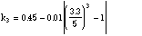
|0.1623 + 0.371r ? 0.696r2 | |
|
k1 |
= |
1.15 (r + 1) |
|
k2 |
= |
0.028 th (r3 /5) |
and Zo is the characteristic impedance of the coaxial cable given by

The off mode impedance (Zoo ) is expressed as
where
The validity range of Equations 1 and 2 is 0 = u = 0.99 for coaxial cables with outer-inner conductor ratio

NUMERICAL RESOLUTION
The study of the structure shown in the diagram, in the electrostatic domain, is based on the resolution of the Laplace's equation in two dimensions for the two modes (even and odd).
div[e r  t V (x, y)] = 0 (3)
Even mode:
|
V |
= |
1V on the two conductors |
|
V |
= |
0 on the shield |
Odd mode:
|
V |
= |
1V on one conductor |
|
V |
= |
1V on the other conductor |
|
V |
= |
0 on the shield |
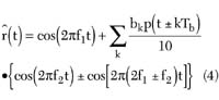
The solution of this equation is found by using the finite element method. This solution represents the distribution of the potential V at the different mesh nodes of the structure. When the potential V is known, the even- and odd-mode impedances can be calculated.
DETERMINATION OF THE ODD- AND EVEN-MODE CHARACTERISTIC IMPEDANCES-COUPLING COEFFICIENT
The lossless lines theory allows us to determine the electric and magnetic fields from the potential V. The electrical energy Wem accumulated in the structure is calculated from the electrical field. All the characteristic impedances (for the two TEM-modes) are deduced easily from the electrical energy Wem . Consequently it is important that the potential V must be found with a high precision.4
ELECTRIC FIELD
The electric field is deduced by simple derivation from the potential V, using the expression
The subscript t indicates the cross section of the structure. The structure accumulates an electrical energy which is deduced from the electric field by
The capacity per unit length is deduced directly from the electrical energy as
V1 and V2 are the fixed potential on the conductors.
The characteristic impedance is calculated from

where
When the even- and odd-mode characteristic impedances are known, the coupling coefficient k is calculated using

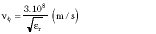
PRIMARY PARAMETERS
The coupling capacity g , and the mutual inductance M, are deduced from the coupling coefficient k as

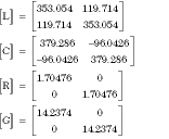
Equation 9 permits the determination of the matrices [L], [C], [R] and [G] using the formulas
L, Co , R and G are the isolated line parameters (already known in the literature).
FEM RESULTS
On the basis of the presented theory, a CAD program is established to calculate the coupling coefficient and matrices [L], [C], [R] and [G] of the coupled lines. These parameters are strongly dependent on the features and properties of dielectrics in which the line conductors are embedded. When the matrices [L], [C], [R] and [G] of the structure are determined, a coupler composed of the two shaped cut coaxial cables is analyzed using an adapted numerical model.
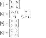
In order to validate the numerical results, the presented structure with outer conductor rb = 1.49 mm, inner conductor rc = 0.255 mm and dielectric permittivity e r = 2.03 is studied. The equipotential lines of the even and odd mode are shown in Figure 2 . Table 1 shows a comparison between the FEM results and those of the literature for different values of the cut depth. Through this comparison, it appears a good correlation between these results and those already published exists.

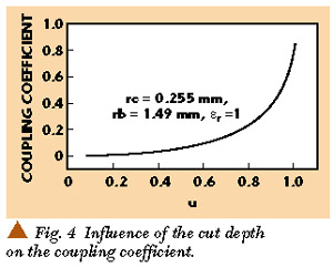
Figure 3 shows the dependence of the cut depth on the even and odd mode characteristic impedances. The two modes have different characteristic impedances for u > 0.2. Figure 4 shows the influence of the cut depth on the coupling coefficient.

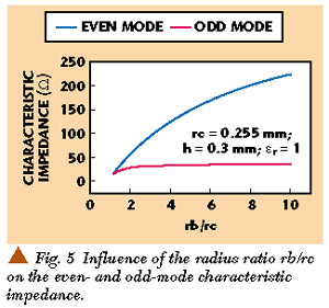
It is interesting to study the influence of the radius ratio rb/rc on the even and odd mode characteristic impedances and coupling coefficient. This influence is shown on Figures 5 and 6 .

DIRECTIONAL COUPLER
In order to successfully study the coupler, it is necessary to determine the matrices [L], [C], [R] and [G] of the two coupled lines with sliced coaxial cable. Thus, the program is applied to analyze the structure having the following features:
Outer conductor rb = 1.49 mm
Inner conductor rc = 0.255 mm
Dielectric permittivity e r = 9
Cut depth h = 0.5 mm
Dielectric losses tgd = 0.0001
Conductivity s = 5.65 • 107 (W m)?1
Operating frequency f = 80 MHz
The obtained results are
Zoe = 49.1342 W
Zoo = 24.2507 W
k = 0.339082
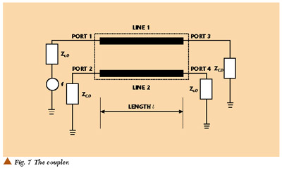
Finally, the analysis is accomplished in the 10 to 160 MHz frequency range, as shown in Figure 7 . All the ports of the coupler are matched with Zco = 50 W .
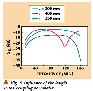
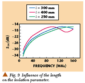
First, the influence of the length of the coupler on the coupling parameter |S12 | and on the isolation parameter |S14 | are studied. This influence is shown in Figures 8 and 9 .
For a length l = 300 mm, the resulting scattering parameters (with respect to 50 W ) are shown in Figure 10 . At 80 MHz, the coupling (-20 log |S12 |) is 12.53 dB, the isolation (-20 log |S14 |) is 18.81 dB.
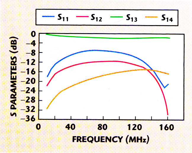
Figure 10. The coupler's S parameters.
In order to modify the response of the coupler, two signal conductors are connected at each end of the coupler with discrete capacitors, as shown in Figure 11 . Figures 12 and 13 show the variation of the coupling and isolation in the 10 to 160 MHz frequency band for different capacitors values, respectively.
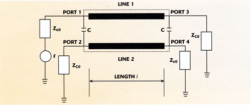
Figure 11. The coupler with compensating capacitances.
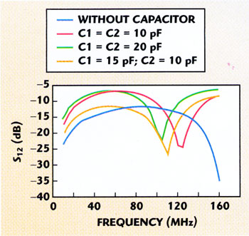
Figure 12. Influence of capacitors on the coupling.
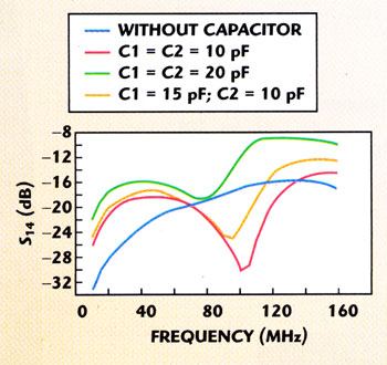
Figure 13. Influence of capacitors on the isolation.
Finally, for C1 = 15 pF and C2 = 10 pF, the scattering parameters of this network versus frequency are shown in Figure 14 . Much better isolation is observed than in the previous case, where at the 80 MHz center frequency the coupling is 13.46 dB and isolation is 21.76 dB. Now the center frequency is lower and it is located in the proximity of 60 MHz.
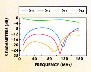
Figure 14. S parameters of the coupler with compensating capacitances.
CONCLUSION
This article has presented the design of an RF coupler using sliced coaxial cable lines. To reach this objective, it was necessary to determine the electromagnetic parameters of the system. In the 10 to 160 MHz frequency band the problem is approximated by the resolution of the Laplace's equation. Its resolution was made by the FEM which allows us the determination of the electromagnetic parameters (coupling coefficient characteristic impedances) of the structure composed of two lines comprised of sliced coaxial cable. The results of the developed CAD program are highly correlated to those previously published. Thus, an important tool for the characterization of the primary and secondary parameters has been established. The numerical model developed remains valid for all configurations of structures of transmission lines propagating the fundamental TEM-mode.
All the curves presented in this article, taking into account the influence of the electrical and geometrical parameters, prove the validity of the developed CAD program. The association of analytical functions to these curves then remains possible. *
References
1.? H. An, O. Monti, R.G. Bossio and K. Wu, "A Novel Type of Low Cost High Performance Coaxial Cables Coupler," 25th European Microwave Coupl. (EuMG'95), 1995.
2.? H. An, R.G. Bossio and K. Wu, "Ultra Wide Band Directional Couplers with Coaxial Cable," Canadian Conference Electr. and Comp. Eng. , 1995.
3.? H. An, T. Wang, R.G. Bossio and K. Wu, "Accurate Closed Form Expression for Characteristic Impedance of Coupled Line with Sliced Coaxial Cable," IEE Proceedings , 1995.
4. N. Benahmed and M. Feham, "Analyse du Couplage Des Lignes de Transmission et Caractérisation de la Diaphonie," CSSA2 '99, Blida, Algeria, 10-12 Mai.