
Effects of a Driver's ACLR on Total ACLR
Sanggee Kang and Heonjin Hong
Electronics and Telecommunications Research Institute (ETRI)
Taejon, Korea
Sungyong Hong
Chungnam National University
Taejon, Korea
The effects of a driver's adjacent-channel leakage ratio (ACLR) on the total ACLR have been tested to investigate the relationship between the ACLR of a driver and a device under test (DUT). The ACLR test results show that the degradation in ACLR is 4.1 to 4.5 dB when both ACLR values are the same. If the difference in ACLR values between a source and a DUT is 12 to 12.5 dB, then there is no degradation in total ACLR.
The capacity of a CDMA system is determined in part by system noise and interference. The system performances are linked to adjacent-channel interference ratio (ACIR) values. ACIR is defined as the ratio of the total power transmitted from a source to the total interference power affecting a victim receiver, resulting from both transmitter and receiver imperfections. The imperfections of the receiver and transmitter are adjacent-channel selectivity (ACS) and ACLR, respectively. ACS is a measure of a receiver's ability to receive a signal at its assigned channel frequency in the presence of a modulated signal in the adjacent channel. Therefore, ACS is the ratio of the receiver filter attenuation on the assigned channel frequency to the receiver filter attenuation on the adjacent-channel frequency. ACLR determines how much the transmitted power is allowed to leak into the first and second neighboring carriers. If the ACLR is low, the efficiency of the spectrum and the capacity of the system are decreased.
All transmitters contain nonlinear components, such as amplifiers and mixers. The output signals of a transmitter consist of amplified input signals and distortion signals caused by the nonlinear characteristics of components in the transmitter. Distortion signals generated in nonlinear components are called intermodulation distortion (IMD). ACLR directly relates to the linearity of a transmitter. Even though the linearity of a transmitter is high, if the purity of the input signal of the transmitter is low, the purity of the output signal of the transmitter becomes low. In this article, the effects of an input signal's ALCR on the ACLR of the output signal of a transmitter are presented. ACLR test results show how the ACLR of the output signals of an amplifier can be determined by the ACLR of the input signal and amplifier.
The linearity of an amplifier for analog transmitting systems is sufficiently represented as IMD and measured with a two-tone IMD test. However, the real signal in a digital mobile system has a different cumulative distribution function from that of tone signals. Therefore, the linearity of an amplifier for a digital mobile system should be tested using an actual signal generated from the signal source for the digital mobile system or the transmitter of the digital mobile system in order to exactly measure the linearity.
Recently, the adjacent-channel power ratio (ACPR) of a transmitter has been used for describing the linearity of the transmitter in a digital mobile system. The measured ACPR values are dependent on the resolution bandwidth. Therefore, ACPR is a meaningful value only with regard to resolution bandwidth (RBW). ACPR does not represent the real power leaked into adjacent channels because it does not include the performance of the receiving filter of a victim receiver. However, ACLR includes the performance of the receiving filter of a victim receiver. Therefore, ACLR is used for describing the linearity of a transmitter in the Third-generation Partnership Project (3GPP) specifications.
Figure 1 shows the spectrum mask of a transmitter, described in the 3GPP specification, according to the output power of the transmitter. The simulation results that compare the ACLR measurement using a raised-root cosine (RRC) filter with a 0.22 rolloff factor (with the ACPR measurement using a 30 kHz RBW) show that the difference between each measurement is 5.6 dB for a 5 MHz offset and 1.52 dB for a 10 MHz offset. Therefore, the ACLR measurement is performed with a proper instrument equipped with an RRC filter with a 0.22 rolloff factor.
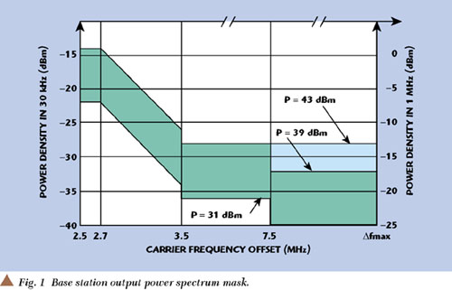
The ACLR requirements of a base station described in the 3GPP specifications are 45 dB for ACLR1 (measured at ±5 MHz offset from the center frequency of the assigned channel) and 50 dB for ACLR2 (measured at ±10 MHz offset from the center frequency of the assigned channel).1,2 The ACLR requirements are derived from the ACIR, causing a one percent capacity loss in the system.3 However, ACLR2 has less of an effect on system performance than ACLR1; therefore, this work focuses on the relationship between the driver's and the DUT's ACLR1.
The high power amplifier mainly determines the linearity of a transmitter. The ACLR specifications described in 3GPP require a linear power amplifier. Even though a linear power amplifier has high ACLR, the ACLR of the input signal of the linear power amplifier is low, thus the ACLR of the output signal of the linear amplifier also becomes low. Therefore, the effect of the transmitter's input signal ALCR on the output signal's ACLR must be considered to implement the transmitter. In addition, it must be determined that the required ACLR of a signal generator does not affect the ACLR of the amplifier in testing the ACLR of a power amplifier.
TEST RESULTS
Figure 2 shows the block diagram for the ACLR test. The signal generator and transmitter tester meet the requirements of 3GPP specifications. The electrical performance of the amplifier used in the ACLR test is listed in Table 1.

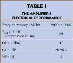
Figure 3 shows the spectrum of the wideband CDMA (W-CDMA) signal used for the amplifier's ACLR test. ACLR1 of the signal is 62.34 dB for +5 MHz offset and 63.21 dB for 5 MHz offset. Figures 4 and 5 show ACLR1 values at the output port of the amplifier with respect to the ACLR value of the input signal and amplifier at ±5 MHz offset, respectively. In general, the nonlinear characteristics of components are not symmetric to the center frequency of output signals in the spectrum domain. Therefore, measurements of the nonlinear characteristics are performed at low and high frequency offsets from the center frequency of output signals. The amplifier's ACLR1 is controlled by adjusting the bias voltage of the amplifier. The controlled ACLR1 value of the amplifier for 5 MHz offset is 55.67, 50.55, 47.95 and 45.10 dB, respectively. In the case where the amplifier's ACLR1 is 55.67 dB, the ACLR1 of the input signal must be 47 dB above to meet the 45 dB ACLR1 requirement. If the amplifier's ACLR1 is 47.95 dB, then the ACLR1 of the input signal must be 51 dB above to keep the ACLR1 requirement in 3GPP. The controlled ACLR1 amplifier values for 5 MHz offset are 56.55, 51.50, 48.45 and 45.72 dB, respectively.


The degradation in ACLR1 according to the difference between the ACLR1 of the input signal and the amplifier is presented. The data are obtained using the ACLR1 values given in the previous two plots. Figure 6 shows the degradation in the amplifier's ACLR1 when the ACLR1 of the input signal is better than the ACLR1 of the amplifier; Figure 7 shows the case where the input signal is less than the ACLR1 of the amplifier. In general, the ACLR of the input signal is better than that of the amplifier. The degradation from the amplifier's ACLR1 is "H 4.5 dB when both ACLR1 values are the same. If the ACLR1 of the input signal is 12 dB above or better than the ACLR1 of the amplifier, then there is no degradation in the amplifier's ACLR. Therefore, the ACLR1 requirement of a signal generator used to measure the ACLR1 of an amplifier is approximately 12 dB greater than the ACLR1 of the amplifier. The data show the degradation in the input signal's ACLR1 when the ACLR1 of the amplifier is better than that of the input signal. In this case, the degradation in the signal's ACLR is approximately 4.1 dB when the ACLR1 of the input signal is the same as that of the amplifier. If the ACLR1 of the amplifier is 12.5 dB greater than that of the input signal, then there is no degradation from the ACLR1 of the input signal. Thus, how much the ACLR degradation occurs in transmitters or amplifiers can be predicted.


CONCLUSION
The effects of the ACLR characteristics of a driver and amplifier on total ACLR have been tested. The ACLR test results show that the degradation in ACLR1 is 4.1 to 4.5 dB when the ACLR of the input signal is the same as that of an amplifier. If the ACLR1 of the input signal is 12 to 12.5 dB greater than that of an amplifier, then the total ACLR1 is the same as that of the amplifier. Therefore, to measure the ACLR1 of an amplifier, a signal source that has an ACLR 12 to 12.5 dB higher than that of the amplifier must be used. Test results presented in this article are useful for determining the required ACLR specification of base station transmitters that compose a base-band modulator, frequency upconverter and power amplifier to meet 3GPP ACLR requirements. These ACLR test results also can be useful for user equipment. *
References
1. 3GPP TS 25.104, Radio Transmission and Reception (FDD) v3.2.0.
2. 3GPP TS 25.141, Base Station Conformance Testing (FDD) v3.1.0.
3. Harri Holma and Antti Toskala, WCDMA for UMTS Radio Access for Third Generation Mobile Communications, John Wiley & Sons, 2000.
 Sanggee Kang received his MSEE from the Dankuk University, Seoul, Korea, in 1994. He joined Samsung Semiconductor & Telecommunication as a design engineer in 1988. Since 1994, he has been involved in the research and development of RF systems for mobile communications at ETRI in Taejon, Korea. His major research interests are high power amplifiers and linear power amplifiers for mobile communications.
 Heonjin Hong received his MSEE from the Chungnam National University, Korea in 1990. Since 1990, he has been involved in research and development of RF systems for mobile communications at ETRI in Taejon, Korea. His major research interests are linear transmitters and receivers for mobile communications
 Sungyong Hong received his doctorate degree in electronic engineering in 1994 from KAIST, Korea. From 1994 to 1996, he worked as an R&D manager at Korea Sangshin Electric. In 1996, he joined the radio science & engineering department at the Chungnam National University in Korea. His research interests are in the area of high frequency circuit design for mobile communication.