
A Novel Design Approach for an RF VNA
Agilent Technologies
Santa Rosa, CA
The vector network analyzer (VNA), the core instrument for RF and microwave device characterization, has kept pace with designers' needs over the years for speed, accuracy and ease of use. Today, VNAs from every manufacturer make measurements far faster than their predecessors of a decade ago. All are equipped with general-purpose interface bus (GPIB) and other interfaces, and their data storage capability has grown from modest to enormous. They are easier to use as well with crisp, colorful displays. However, as far as performance is concerned there hasn't been a quantum leap by any VNA manufacturer in many years. The just-introduced PNA Series of VNAs arguably makes this leap by setting new benchmarks in measurement speed and noise performance. (The above photo depicts the 3, 6 and 9 GHz models.)
The PNA Series VNAs are the most sophisticated analyzers ever produced by Agilent or its predecessor, Hewlett-Packard. To achieve performance that is up to 35 times faster than the industry-standard model 8753 VNA with trace noise as low as 0.0005 dB, the company changed its design approach, beginning with the use of mixers rather than samplers, the most conventional choice. This level of performance was determined to be necessary for the PNA to be considered an "all-new" successor to the HP 8753 series VNAs, which were introduced in 1986 and have been continually updated over the years. The major improvements, in short, can be summed up as:
· measurement speed as fast as 35 µs per point -- between six and 35 times faster than the 8753ES;
· trace noise as low as 0.0005 dB;
· 128 dB dynamic range, increasing to 143 dB when couplers are bypassed or reversed;
· 3, 6 and 9 GHz measurement ranges;
· four mixer-based measurement receivers for TRL error correction;
· segmented sweeps that increase speed by collecting data only at specific points and optimizing bandwidths;
· simplified electronic calibration (E-Cal);
· embedded tutorials, context-sensitive help, drop-down menus, and mouse or front-panel control; and
· automation via Standard Commands for Programmable Instruments (SCPI) or high speed Component Object Model (COM)/Distributed Component Object Model (DCOM) commands.
µW + PC = CONNECTIVITY
The PNA Series uses the Microsoft Windows 2000 Professional operating system, which is exceptionally stable and tailored for the networked environment. This capability allows the PNA Series instruments to integrate via the network like any other office or industrial equipment within the PC-centric world. Windows 2000-based automated test tools such as COM/DCOM and programming languages, as well as applications for post-processing of measurement data, all can be used by the PNA Series instruments without the need for an external PC or instrument controller.
For example, a group of network analyzers on the production floor can each run programs to control their individual test stations. The data collected at each test station can be stored locally on the network analyzer or on a remote file server accessible via the local area network (LAN). For computation-intensive programs or programs that require considerable memory resources, the application can run on a fast external computer that also controls the instrument, or some data processing can be performed on the network analyzer and some on an external computer.
Engineers can create test processes using familiar SCPI or COM and DCOM commands and execute them over a LAN interface or within the instrument. SCPI also can be executed over GPIB. The analyzer's firmware provides many programmable objects, or automation entry points, that respond directly to COM statements. COM programming and IntelliSense (as integrated within Windows 2000) make it easier to write test code on multiple hardware or software platforms, and makes the source code much easier to understand and debug. Programs in COM and DCOM can also transfer data up to four times faster than SCPI.
PERFORMANCE IMPROVEMENTS
Measurements requiring 100 dB of instrument dynamic range can be made with a 40 kHz bandwidth on the PNA series instruments rather than the 1 kHz bandwidth of the 8753ES, yielding a sweep speed 16 times faster than the 8753 analyzer. For measurements that require 120 dB of dynamic range, the PNA Series is 35 times faster than the 8753ES, and sweeps that take 43 s on the 8753ES take just 1.2 s on the PNA Series instruments.
By removing the front-panel RF jumpers to directly access the measurement receivers (bypassing the internal directional couplers), more than 143 dB of dynamic range can be achieved, providing insight into a component's performance that was simply unavailable before. With a 40 kHz IF bandwidth, the PNA Series VNAs can sweep six times faster than the 8753ES, updating the measurement 80 times every second. With a 10 Hz bandwidth, the PNA Series instruments achieve over 128 dB of dynamic range at the test set ports with an insignificant 0.0005 dB RMS of trace noise.
The PNA Series VNAs provide several choices for saving instrument states or measurement data. For local storage, operators can use either the analyzer's internal hard disk or 3-1/2-inch diskette drive or an optional USB-compatible CD-RW. The Windows network-drive mapping features and LAN interface allow data to be saved directly to remote PCs or file servers, making it easier to develop statistical-process-controlled manufacturing environments. Users can generate hard copy on any printer on the LAN, or locally via USB or parallel interface.
The LAN, serial, parallel or GPIB interfaces can also be used to control other equipment such as power meters, signal sources and spectrum analyzers in the test station directly from the network analyzer. Test software can employ Windows-based programs such as Visual Basic, Visual C++, LabVIEW or Agilent VEE. The LAN interface also makes it possible to conduct remote troubleshooting by reviewing measurement results and controlling the analyzer from anywhere on the LAN -- or anywhere in the world -- via the Internet.
In addition to their exceptional RF performance, the instruments have simplified calibration through E-Cal and CalWizard, and many features designed to streamline the test process. If a segmented sweep is employed, the analyzer measures the device response only at defined frequency segments, skipping unneeded data and delivering high frequency resolution where desired, such as in a filter passband. Variable IF bandwidths enable wide bandwidths and fast sweeps to be performed in segments that require little dynamic range, and narrow IF bandwidths to be used in segments that require high dynamic range.
The new instruments can also improve test throughput when used to evaluate devices that require up to four instrument setups for complete characterization. The PNA Series VNAs provide up to four measurement channels, each with its own stimulus and response parameters. Instead of recalling separate instrument states, one instrument state can be recalled that contains all the measurement channels. Thus, only one instrument state is required to be recalled for an entire production run, instead of four per device. When this time savings is multiplied by a large number of device measurements, overall test throughput increases dramatically.
MIXING IT UP
The traditional VNA, as shown in Figure 1 , uses dual directional couplers for signal separation. (Resistive splitters may also provide the reference signals.) Samplers are attractive because of their wide bandwidth, flat frequency response, excellent stability and good compression. As a result, they have been a staple of vector measurements for years. Samplers also simplify LO design because the LO consists only of a low frequency synthesizer followed by a sampling pulse generator. However, the sampler approach has two major character flaws: noise floor and trace noise are high, a result of high sampler noise figure, and phase locking can be tricky and time-consuming because of the possibility of locking to the wrong tooth of the sampler LO comb.

Achieving an exceptionally low noise floor was one of the primary goals in designing the PNA Series instruments, so a mixer-based approach was chosen instead. In this design, shown in Figure 2 , the samplers are replaced with mixers, and the low frequency pulsed LO is replaced with a high frequency sinusoidal LO. The conflicting requirements for greater sensitivity and higher power-handling capability are met with a configurable test set; that is, the front-panel reference and receiver jumpers are a standard feature, and the source jumpers and 5 dB attenuator with a maximum of 35 dB are available as an option. Although a network analyzer can be built with just one reference receiver, having two receivers enables TRL calibration, which is very useful for on-wafer device probing. The second reference receiver allows source leveling after the switch, which improves power level accuracy, source match and measurement repeatability.

Mixers have lower noise figures and compression characteristics equivalent to samplers; therefore, the mixer-based approach produces an instrument with greater dynamic range. In the PNA Series VNAs, the noise floor dropped 15 dB simply by utilizing mixers rather than samplers. The PNA instruments use fundamental mixing to 3 GHz, and third-harmonic mixing from 3 to 9 GHz. In contrast, sampled systems can convert on LO harmonics greater than 100. Another benefit of low order mixing is superior system spurious and residual performance, which reduces analyzer trace noise and increases usable dynamic range.
Mixers also make the analyzer much faster. For example, the time required to make high dynamic-range measurements is inversely proportional to the measurement bandwidth. For example, a sweep performed in a 10 Hz bandwidth will take 10 times as long as a sweep made in a 100 Hz bandwidth. If the system noise figure is lowered by 10 dB through the use of mixers instead of samplers, or if the source power is increased by 10 dB, the 100 Hz bandwidth will yield the same signal-to-noise ratio as the 10 Hz bandwidth did before either improvement was made. However, in either case measurement speed increases tenfold. If power is increased by 10 dB and noise figure is improved by 10 dB, a 1 kHz bandwidth can be used, and measurement speed may be increased one hundred fold.
Using mixers instead of samplers speeds up the system for other reasons as well. The mixing order is low; therefore, fewer false responses enter the phase-lock circuitry. False locking is avoided and phase lock acquisition proceeds quickly. The LO and source now have the same tuning sensitivities; thus, open-loop frequency tracking of the LO and source is greatly improved. This reduced frequency-tracking error directly lowers closed-loop frequency error, speeding up phase lock acquisition, sweeping and stepping.
TUNING OUT MIXER BOUNCE
Spurious responses caused by a phenomenon called mixer (or sampler) bounce can seriously degrade the sensitivity of a network analyzer. Figure 3 shows the mechanism by which mixer bounce occurs, and an insertion loss measurement of a low loss filter that has a highly reflective stopband is shown in Figure 4 . Whether the converters are mixers or samplers, the mechanism is the same. Referring to the traditional VNA configuration, assume the source frequency is in the filter stopband and follow the dashed line starting at the source. Source energy reflects from the filter input, enters reflection receiver A and mixes with harmonics of the LO.
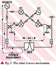

The resulting products N x LO ± IF exit A, pass through the filter, remix with LO harmonics in transmission receiver B and create false responses. Source power is +10 dBm, and IF bandwidth is 10 Hz with no averaging. The largest response, at 1.8 GHz, is produced by the 1 x LO + 1 x RF term from A converting with 2 x LO in B. Reference receiver R1 will also generate mixer bounce, but at a much lower level than A, because of splitter isolation.
Two methods are used in the PNA Series VNAs to reduce mixer bounce. Reverse isolation from each mixer to its respective RF input is increased as much as possible, so the mixing products cannot leave the reflection receiver. If even more mixer-bounce reduction is needed, the reflection receiver can be disabled entirely while making a transmission measurement. Turning off the A or B mixers in an alternating fashion requires twice as many sweeps to gather all four S-parameters, and ultimately residual mixer bounce from the reference receiver can limit dynamic range. The same filter measured after mixer-bounce improvements were made is shown in Figure 5 . Ten sweeps were averaged to reduce the noise floor and verify the absence of mixer bounce. Since mixer bounce is coherent from sweep to sweep like crosstalk, it will not average-down like noise.

OPTIMIZING FOR SPEED
In optimizing a network analyzer for speed, it quickly becomes obvious that all elements of the instrument must be improved, since they are all in some way interrelated. For example, faster measurement hardware is useless if the central processing unit (CPU) or display cannot keep up with the data. Speeding up the RF source without a commensurate increase in LO speed negates this advantage as well. In short, resources must be applied in a balanced way to accelerate the measurement hardware, CPU, display and all associated control firmware.
The PNA data acquisition engine, shown in Figure 6 , consists of an agile RF source locked to an agile fractional-N-based LO, a high performance test set and receiver chain, digital signal processing (DSP) hardware control and data conditioning, all orchestrated by the instrument firmware. A fast-tuning YIG source oscillator provides the necessary frequency agility for fast sweeping and stepping, achieved primarily by reduced main tuning coil inductance. This low inductance allows rapid changes in main coil current (and thus frequency) without the need for high coil drive voltages. The agile synthesized LO has similar tuning characteristics to the YIG source, and this precise frequency tracking makes possible the instrument's high speed sweeping and stepping.

Frequency errors take time to settle out. The measurement process cannot begin until both the LO and source frequencies are sufficiently settled. The high open-loop frequency accuracy of the PNA enables fast phase lock acquisition, which in turn allows rapid initiation of data-taking. The YIG source also has excellent phase noise performance, which reduces the instruments' trace noise.
The sweep speed of the analyzer is great enough (up to 600 GHz/s) that it is possible to sweep too fast for DUTs that have long group delays. The frequency at the input of the DUT when sweeping is different than the frequency at the output of the DUT, and this frequency difference is proportional to DUT group delay and sweep rate. As the DUT output frequency moves off the center of the system resolution bandwidth, amplitude and phase errors increase.
To preserve this high speed measurement capability while improving accuracy, the sweep speed can be slowed or reference path delay can be added. The reference length extension works only for constant-delay DUTs. Stepping with an appropriate dwell time yields the highest data accuracy. The PNA's fast stepping capability and segment sweep mode allow for exceptional throughput optimization.
A LEAP IN DYNAMIC RANGE
Dynamic range can be increased by increasing source power. An instrument configuration for characterizing a high power amplifier with two-port calibration is shown in Figure 7 . The external booster amplifier, reference coupler and reference attenuator provide high source power. The internal port 1 coupler is used for reflection measurements, and the 35 dB, five-step attenuator ensures that the power from the coupled arm of port 1 remains within the allowable input power range of the receiver. A high power output coupler and internal 35 dB attenuator handle the high transmitted power, and a high power isolator provides a good termination to the amplifier output and keeps dangerous levels of power out of the analyzer.

The PNA Series instruments allow the transmitted coupler to be reversed, as shown in Figure 8 , which dramatically increases transmitted receiver sensitivity and is very useful when characterizing filters used in T/R duplexers and other applications in which high-performance filters are used. The resulting reduction in system noise figure can also be employed to increase measurement speed. Greater dynamic range can also be achieved by inserting a low noise amplifier (LNA) that has very stable amplitude and phase characteristics before the instrument's receiver. The dynamic range of the PNA VNAs can be increased beyond 143 dB and even further with the optional LNA.
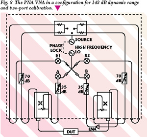
These extended-sensitivity measurements require attention to power levels during calibration and measurement in order to prevent transmitted receiver or LNA overload. Power is reduced for the through calibration and when measuring over low insertion loss frequency segments, and increased for high insertion loss frequency segments. These differing power levels, along with imperfect reference and measurement receiver linearity, allow small linearity errors to occur. However, prudent selection of receiver power level allows these errors to be traded off for dynamic range and vice versa.
CONCLUSION
The design choices made when creating the PNA Series VNAs should cement their validity to greater degrees as marketplace demands for speed and sensitivity increase, as they have throughout the last decade. In addition to the instruments' enhanced RF performance, integration of the Windows 2000 Professional operating system allows the instruments to be integrated in the vast majority of enterprise-wide manufacturing networks. Together these attributes are key to the longevity expected for the PNA Series instrument family. Orders now are being accepted for the PNA Series RF VNAs. The E8356A 3 GHz model is priced at $43,000, the E8357A 6 GHz model at $49,000 and the E8358A 9 GHz model at $55,000.
Agilent Technologies,
Test and Measurement Organization,
Santa Clara, CA (800) 452-4844.