
Flexible cable is designated by an RG number (such as RG-58 and RG-59), whereas semi-rigid is designated by a number only, that number being the outside diameter of the cable. Common sizes (in in.) of semi-rigid cable are 0.020, 0.034, 0.047, 0.056, 0.070, 0.085, 0.141, 0.215, 0.250 and 0.325. The three sizes most widely used are 0.085, 0.141 and 0.250. The large majority of semi-rigid cables used in equipment are 0.141 cables.
The other two common types of semi-rigid cable, 0.085 and 0.250, are used in applications where 0.141 may not be suitable. The 0.085 cable is used when there is very little room in which to maneuver, so the bends in the cable must be very small. This small-diameter cable fits this need, but at the price of higher attenuation than its 0.141 counterpart. The power-handling capability of the 0.085 cable also is less than that of the 0.141, which is understandable, since it is much smaller and there is less area to dissipate power.
The 0.250 semi-rigid cable is used primarily for higher power applications, because it has much more area to dissipate power. For comparison, consider the power-handling capability of the three sizes of cable at 1 GHz. The 0.085 cable is rated at 222 W, the 0.141 cable is rated at 600 W and the 0.250 cable is rated at 1200 W (each is CW power). The 0.250 cable also exhibits lower attenuation. At 1 GHz, the 0.085 cable has 0.187 dB/ft of attenuation, 0.141 cable has 0.116 dB/ft and 0.250 cable has 0.073 dB/ft. Its drawback is its size; it requires a lot of room to make a bend. Thus, 0.250 cable is used mainly for straight runs in high-power applications.
|
|
Attenuation (dB/100 ft) |
Power (W) |
||||||||
|
Frequency (GHz) |
0.4 |
1.0 |
3.0 |
5.0 |
10.0 |
0.4 |
1.0 |
3.0 |
5.0 |
10.0 |
|
Cable Type |
||||||||||
|
0.141 |
7.2 |
11.6 |
21.5 |
28.8 |
44.5 |
1000 |
600 |
310 |
230 |
160 |
|
RG-58 |
11 |
20 |
41 |
- |
- |
75 |
44 |
22 |
15 |
- |
Semi-rigid cable has many superior electrical properties over flexible cable. In all cases, it can handle more power and exhibit less loss than a flexible cable of comparable size. For example, a comparison of a length of RG-58 flexible cable with a length of 0.141 semi-rigid cable at five frequencies is shown in Table 2. These two cable types have similar outside diameters (the outer conductor of the RG-58 is 0.150 in.). Attenuation at 3 GHz, for example, is 0.215 dB/ft for 0.141 cable versus 0.41 dB/ft for RG-58. At that frequency, the 0.141 cable can handle 310 W, while the RG-58 cable can handle only 22 W. The RG-58 cable is also not specified at all for attenuation at 5 or 10 GHz and is not specified for power-handling capability at 10 GHz. Recall that all transmission lines have an upper frequency limits since they all act like lowpass filters. That is clearly indicated in Table 2 for the RG-58 cable.
The numbers in Table 2 might lead one to ask, “Why ever use flexible cables?” First, semi-rigid cables cost considerably more than flexible cables; an important consideration, especially in the commercial market. Second, for testing applications, semi-rigid cables are not very practical. Most tests require many connect/disconnect operations, which can put strain on the cables. Also, as the tests change in a lab, there are different positions for the cables that are formed much better with flexible cables. Third, in some finished products, the cables must meander through the chassis to various locations. Semi-rigid cables are not suitable for those applications in many cases.
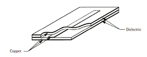
Figure 9 Typical semi-rigid cable assemblies.
Strip transmission line (stripline)
The terms strip transmission line, stripline, tri-plate and sandwich line all refer to the same type of transmission line. The term most commonly used is stripline. Stripline is different from, yet also similar to, flexible and semirigid cables. As a matter of fact, stripline actually evolved from coaxial transmission line. The stripline shown in Figure 9 appears to be similar to a coaxial cable; it looks like a coaxial cable that has been flattened.
The coaxial structure shown in Figure 10a is a typical center conductor surrounded by a dielectric with a shield completely around the entire structure. Figure 10b is a side view of a stripline structure. If pressure is applied at the top and bottom of the coaxial structure in Figure 10a, the circular structure deforms into an oblong shape rather than a concentric circular form. The electric field lines go from the center conductor to the outside shields of the structure. With further pressure, the two ends eventually split and break. What remains is a top ground (outside shield), a bottom ground and a rectangular center conductor, the same structure shown in Figure 9.
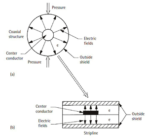
Figure 10 Typical semi-rigid cable assemblies.
In both Figures 9 and 10, it can be seen that stripline actually is two circuit boards sandwiched together (hence the term sandwich line). There is a ground (copper) on the top and a ground on the bottom, with the actual circuit in between and surrounded by a dielectric medium. The circuit is what is termed the center conductor in Figure 10 and is the straight line running through the center of the device in Figure 9. In the coaxial structure of Figure 10, the center conductor is surrounded by a dielectric material. In the stripline structure, each circuit board contains a dielectric layer, which is the same for both boards, that is, the center conductor is surrounded by the same dielectric, top and bottom. In its simplest form, a piece of stripline has a lower circuit board with a circuit etched on one side of a dielectric layer and a complete ground plane (covering the entire circuit board) on the other. The top board has a similar ground plane on one side of the dielectric layer and no metallization on the other side. The two boards are permanently bonded together with an adhesive to form a monolithic structure with two ground planes, separated by a virtually continuous dielectric interrupted only by the center conductor in between.
It is necessary to clarify the term ground plane. In conventional low-frequency, DC and digital circuits, a ground is a point on a chassis where wires carrying return current are terminated to ensure a common potential. In RF and microwave circuits, electromagnetic waves sent down transmission lines require an entire (continuous) plane or large area of ground rather than a single point. High frequency signals have periodicities that are perturbed by point grounds. That is why circuit boards have copper plating across their entire outer surfaces.