
Measurement Results
With the development of the 2.856 GHz DRO, it soon became apparent that the sensitivity of the then used phase noise test set21 was insufficient. Figure 12 shows a measurement, taken with the maximum number of correlations (and minimum offset start frequency), extending over 36 hours. Yet, the plot still shows insufficient sensitivity between 10 kHz and 1 MHz, as well as artefacts around 30 kHz.
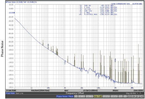
Figure 12 Measurement of the 2.856 GHz DRO using a test setup with maximum sensitivity (36 h).
Also development work on the DROs was tedious, as PN measurements took at least 20 minutes in order to come up with a useable value at 1 kHz offset. Since the DRO’s -125 dBc/Hz at that offset are just 10 dB below the test set’s synthesizer noise, a manageable number of correlations yields an acceptable result (compare to Figure 10).
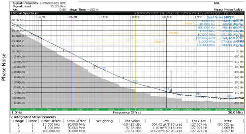
Figure 13 Measurement of the 2.856 GHz DRO using R&S test setup with about 2.5 h measurement time.
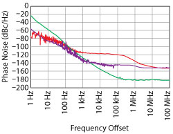
Figure 14 Comparison of various test setup phase noise compared to 3.9 GHz DRO.
The situation much improved with the availability of a phase noise measurement system with much lower noise internal reference sources. Figure 13 shows a measurement of the 2.856 GHz DRO with this instrument taken over about 2.5 h of measurement time, showing excellent accuracy. Figure 14 shows 20 dB less phase noise (purple trace) over the offset frequency range from1 kHz to 100 kHz, compared to another instrument (red trace). Recalling that the cross correlation technique reduces test set noise by 5 dB for every 10-fold lengthening of measurement time, the 20 dB reduction in synthesizer phase noise translates to a potential gain in measurement speed of four decades.
Going back to Figure 13, the alert designer will notice that the phase noise of this DRO does not decay with 20 dB to 30 dB/decade into the noise floor, as theory demands. The measurement therefore hints at extra noise polluting the signal for offsets above 10 kHz, suggesting potential for improvement, not evident from Figure 12. Further investigations revealed a number of simple to implement changes that were incorporated into the next design of the 3.9 GHz DRO. Additional performance was gained by tweaking the design through phase noise optimizations, enabled by the measurement speed of the system that makes useable phase noise data at 1 kHz/10 kHz offset available in less than 10 seconds, even at those challenging phase noise levels. The measurement results of the 3.9 GHz DRO are shown in Figure 15.
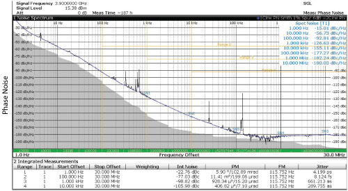
Figure 15 Measurement results for the 3.9 GHz DRO.
With both designs built around dielectric resonators with a loaded Q of 15,000, phase noise numbers at 3.9 GHz can be expected to be 2.7 dB = 20log10(3.9/2.856) higher than at 2.856 GHz. Instead, for offsets over 1 kHz, the 3.9 GHz design shows even lower phase noise. In terms of jitter, the optimizations yielded a 40 percent reduction, bringing jitter down to 0.66 fs (integrating phase noise over 1 kHz to 30 MHz) and 0.29 fs (10 kHz to 30 MHz).
Conclusion
Sub-femtosecond jitter microwave sources were developed for two of the relevant frequencies in X-FEL electron beam accelerators. None of the critical design decisions taken are novel, but rather adhere to long known principles. Use of modern, low noise components and techniques, as well as careful optimization of all building blocks was key to the achieved performance.
It should be pointed out that the resulting designs are stable and reproducible commercial products, with typical noise data not differing by more than a few dB. With the phase noise of the realized oscillators being, at most offsets, decades below the intrinsic noise of most measurement systems, such low noise sources can only be measured using cross-correlation techniques. Yet, the required sources to compare the DRO against must be as low noise as possible, to not overburden the cross-correlation capabilities, bearing in mind that every 5 dB of necessary test set noise reduction require a 10-fold measurement time.
Acknowledgment
The preceding work would not have taken place without my sales partner Bernd Rupp, putting me in touch with a number of supportive people and drumming up enough interest in a commercial product. Also, I am indebted to Jesse Searls (formerly with Poseidon Scientific Instruments) for encouraging me, to try my hand on these types of ultra-low noise sources. I am very thankful for the support of Frank Lin of Skyworks in finding the optimum resonators and Takahashi Okawa of Daiken Chemical Co. for valuable discussion.
References
- GDRO2856 Datasheet, Ingenieurbüro Gronefeld, www.gronefeld.de.
- GDRO3900 Datasheet, Ingenieurbüro Gronefeld, www.gronefeld.de.
- DESY Homepage, www.desy.de/index_eng.html.
- Pohang Accelerator Laboratory (PAL), http://pal.postech.ac.kr/paleng.
- “FLASH Looks Deep into the Atom,” DESY-News, www.desy.de/news/news_search/index_eng.html?openDirectAnchor=758.
- “First Atomic Structure of an Intact Virus Deciphered with an X-ray Laser,” DESY-News, www.desy.de/news/news_search/index_eng.html?openDirectAnchor=1240.
- “New ‘Molecular Movie’ Reveals Ultrafast Chemistry in Motion,” SLAC-News, www6.slac.stanford.edu/news/2015-06-22-new-%E2%80%98molecular-movie%E2%80%99-reveals-ultrafast-chemistry-motion.aspx.
- “High Speed Camera Snaps Bio-Switch in Action,” DESY-News, www.desy.de/news/news_search/index_eng.html?openDirectAnchor=1138.
- “Undulator,” Wikipedia, https://en.wikipedia.org/wiki/Undulator.
- J. Piekarski and K. Czuba, “The Method of Designing Ultra-Low Phase Noise DROs,“ MIKON 2010.
- W. J. Tanski, “Development of a Low Noise L-Band Dielectric Resonator Oscillator,” IFCS 1994.
- P. Stockwell, D. Green, C. McNeilage and J.H. Searls, “A Low Phase Noise 1.3 GHz DRO,” IFCS 2006.
- J. Everard and K. Theodoropoulus, “Ultra-Low Phase Noise Ceramic based DROs,” IFCS 2006.
- M. M. Driscoll, “Low Noise, VHF Crystal Oscillator Utilizing Dual, SC-Cut Resonators,” UFFC 1986.
- D.B. Leeson, “A Simple Model of Feedback Oscillator Noise Spectrum,” Proc. of IEEE, Vol. 54, 1966.
- T. E. Parker, “Current Developments in SAW Oscillator Stability,” ASFC 1977.
- A. Effendy and W. Ismail, “Wide Tuning Range Dielectric Resonator by Optimizing the Tuning Stub Characteristic Impedance,” APMC 2012.
- M. J. Loboda, T. E. Parker and G. K. Montress, “Temperature Sensitivity of Dielectric Resonators and Dielectric Resonato Oscillators,” AFCS 1988.
- Phase Noise Analyzer APPH20G, AnaPico Ltd.
- Phase Noise Analyzer HA7062B/C, Holzworth Instrumentation Inc.
- Signal Source Analyzer E5052B, Keysight Technologies Inc.
- Phase Noise Analyzer NXA, Noise eXtended Technologies S.A.S.
- Phase Noise Analyzer FSWP, Rohde & Schwarz GmbH & Co. KG.