
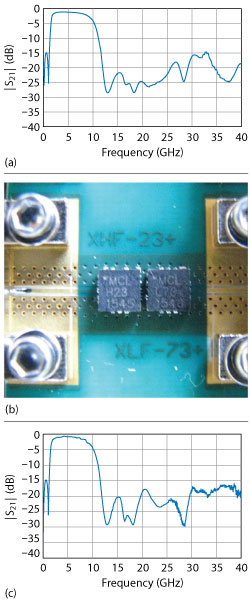
Figure 2 Simulated response combining XHF-23+ and XLF-73+ (a), devices in the test fixture (b) and measured results (c).
Case 3: Confirming Stopband Rejection to 40 GHz Without Re-Entry
Cases 1 and 2 illustrate that cascaded reflectionless filters can achieve ultra-wide passbands, enabling bandwidths at least to a full decade, to support the bandwidth requirements of UWB applications. Another concern for system designers is the potential for “re-entry” out of the band at higher frequencies. Such unintentional radiation can potentially interfere with signals at neighboring frequencies and violate FCC rules. Therefore, UWB filters must exhibit good stopband rejection without re-entry to a very high frequency. In part due to their fabrication using MMIC technology, reflectionless lowpass filters provide stopband rejection extending to 40 GHz. Many conventional filter approaches would suffer re-entry over this bandwidth.
In this case, a highpass model (2.01 to 10.1 GHz) and lowpass model (DC to 7 GHz), both single-section designs, are combined. Simulation results for the combined filter are shown in Figure 3a, demonstrating a 3 dB passband from 1.6 to 10 GHz (6.25:1 or 145 percent bandwidth). Stopband rejection remains better than 15 dB up to 40 GHz without re-entry. Figure 3c plots the measured insertion loss of the test board shown in Figure 3b. The measured response shows a 3 dB passband from about 1.7 to 9.3 GHz (5.5:1 or 138 percent bandwidth), with stopband rejection well above 15 dB up to 40 GHz, confirming that this technique can be used in UWB applications without unintentional out-of-band emissions due to re-entry.
Case 4: Adding LTCC Filters to Sharpen Selectivity
We have shown that reflectionless filters can be combined to achieve ultra-wide passbands and that this approach provides excellent stopband rejection up to 40 GHz without re-entry. To come closer to real world requirements of UWB systems under FCC specifications, it may be necessary to sharpen the transition to conform to the FCC spectral mask.
The absorptive characteristic of reflectionless filters means that they are not only cascadable with other reflectionless filters, but with all manner of conventional filters. This hybrid approach enables the desired wideband response while incorporating the selectivity of another filter technology. In this case, a two-section, highpass reflectionless filter (2.9 to 8.7 GHz) is combined with a lowpass LTCC filter (DC to 10.6 GHz) to use the greater selectivity of the latter. Simulation results are shown in Figure 4a, along with the FCC spectral mask for indoor UWB transmissions. This combination exhibits a passband from 2.4 to 10.9 GHz (4.5:1 or 128 percent bandwidth). Deep rejection at the lower stopband, below 2.4 GHz, keeps transmissions at neighboring frequencies, such as GPS at 1.6 GHz, clean of emissions. While the data for the LTCC filter stops at 15 GHz, it is clearly approaching some re-entry at that point. This is a trade-off when incorporating a different filter technology.
The test board for this filter combination is shown in Figure 4b and the measured insertion loss is shown in Figure 4c. It has a measured 3 dB passband from about 2.45 to 10.9 GHz (4.5:1 or 127 percent bandwidth), consistent with the simulation. The combination with the LTCC filter introduces a few noteworthy differences from the previous cases. First, the insertion loss suffers some re-entry around 25 GHz, enough to just cross the FCC limit. Also, the return loss in the upper stopband (not shown) degrades because the LTCC filter is fully reflective in its stopband. Overall, the filter approaches the desired response for real world UWB transmission, yet is still wider than ideal. A similar approach with the right combination of filters may come closer to the ideal filter behavior.
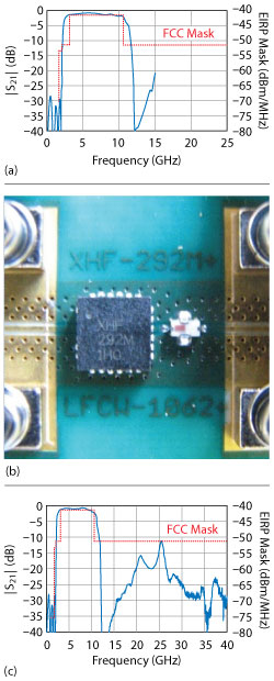
Figure 4 Simulated response combining XHF-292M+ and LFCW-1062+ vs. FCC spectral mask for UWB indoor transmissions (a), devices in the test fixture (b) and measured results (c).
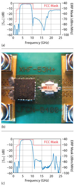
Figure 5 Simulated response combining XHF-53H+ and LFCN-8400+ vs. FCC spectral mask for UWB indoor transmissions (a), devices in the test fixture (b) and measured results (c).
Case 5: UWB Filter Meeting the FCC Emission Mask for Indoor UWB Transmission
To realize a filter response closer to the ideal for real world UWB transmission, careful model selection leads to the combination of a three-section, highpass reflectionless filter (5 to 11 GHz) and a lowpass LTCC filter (DC to 8.4 GHz). A simulation of this filter combination is shown in Figure 5a, including the FCC mask for indoor UWB transmission. The simulated 3 dB passband is from 3.9 to 9.4 GHz (2.4:1 or 83 percent bandwidth). Although the LTCC filter does show some re-entry in the upper stopband, it is not significant enough to become a secondary passband, remaining well below the FCC mask.
The test board is shown in Figure 5b and the measured insertion loss is in Figure 5c. The filter response exhibits a 3 dB passband from 4.25 to 9.15 GHz (2.2:1 or 73 percent) and conforms well to the FCC spectral mask. Again, the reflectionless LTCC hybrid approach comes with some tradeoffs that warrant mentioning. First, as expected, the filter exhibits reflective behavior in the upper stopband and return loss degrades above 9 GHz. Secondly, while the upper stopband achieves excellent rejection to 25 GHz, it suffers some re-entry around 30 to 35 GHz. A different lowpass filter model may be needed to suppress this re-entry at higher frequencies. Nonetheless, this example illustrates how reflectionless filters can be successfully cascaded with other filter designs to achieve the desired passband shape for UWB communications.
CONCLUSION
The examples in this article show how reflectionless filters provide a novel and highly viable approach to filter design for UWB applications. They all employ standard, catalog filters available from Mini-Circuits. Mini-Circuits offers over 50 reflectionless filter models from stock, and custom designs are available to meet exact application requirements.
The approach demonstrated provides designers several practical advantages over previously studied approaches using microstrip structures. In addition to the electrical properties that make reflectionless filters ideal for UWB, the filters are smaller, less costly and more repeatable compared to competing technologies, making them suitable candidates for use in commercial applications where volume manufacturability may be a requirement.
Mini-Circuits is currently developing new designs with lowpass and highpass filter dice cascaded within a single package to reduce size, lower cost and minimize parasitic effects.
While this article discussed the suitability of reflectionless filters for UWB applications, it should serve to broaden the reader’s understanding of these innovative products as flexible building blocks with numerous applications in RF system design, many of which still remain to be explored.
References
- J. M. Wilson, “Ultra-Wideband: A Disruptive RF Technology?,” Intel Research & Development, Version 1.3, September 2002.
- C. Hsu, F. Hsu and J. Kuo, “Microstrip Bandpass Filters for Ultra-Wideband (UWB) Wireless Communications,” IEEE MTT-S International Microwave Symposium Digest, October 2005.
- C. Cansever, “Design of a Microstrip Bandpass Filter for 3.1-10.6 GHz UWB Systems,” Thesis, Syracuse University College of Engineering and Computer Science, 2013.
- J. Pan, “Medical Applications of Ultra-Wideband (UWB),” Washington University, St. Louis, April 2008, www.cse.wustl.edu/~jain/cse574-08/ftp/uwb/index.html.
- L. Zhu, S. Sun and W. Menzel, “Ultra-Wideband (UWB) Bandpass Filters Using Multiple-Mode Resonator,” IEEE Microwave and Wireless Components Letters, Vol. 15, No. 11, November 2005, pp. 796–798.
- A. Sheta and I. Elshafley, “Microstrip Ultra-Wide-Band Filter,” PIERS Proceedings, March 2011, pp. 198–200.