
Return loss: To check the cable return loss or SWR, connect one end of the cable to the VNA and a load to the other end (see Figure 2). Ideally, display |S11| in dB on one trace window and SWR on another window, as shown in Figure 3. Find the maximum return loss value (closest to 0 dB) and corresponding SWR and compare the measured data with the cable specifications. This measurement is only as good as the load at the end of the cable, so use a known good load with a return loss better than the expected return loss of the cable. In the example shown in Figure 3, the measured return loss is 23.1 dB (1.16:1 SWR), confirming the cable is within its specified return loss of greater than 20 dB through 7.5 GHz.
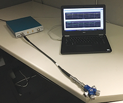
Figure 2 Measuring the cable’s return loss using a known load.
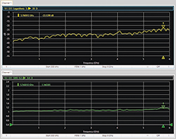
Figure 3 Checking cable quality by measuring return loss and SWR using a VNA.
Insertion loss: To check the cable’s insertion loss, with the cable still connected to the same VNA port, replace the load with a short and measure |S11|. While a typical insertion loss measurement requires both ports of the VNA, recall that a short circuit produces a full reflection, and we can derive the cable’s loss by dividing the |S11| magnitude in dB by two (see Figure 4). This approach keeps the cable straight and does not require additional cabling. In this example, the measured |S11| is ‐1.79 dB, meaning the cable’s insertion loss is approximately 0.9 dB, which is less than the cable’s specification of 1.05 dB and well within the desired insertion loss of less than 2 dB.
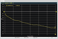
Figure 4 Determining the insertion loss of a cable by measuring the |S11| with the cable shorted.
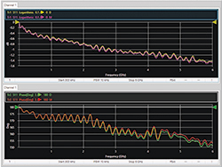
Figure 5 Using a shorted cable assembly and the VNA’s data-to-memory capability, changes in the magnitude and phase of a cable can be measured as the cable is flexed.
Stability of insertion loss and return loss: The next step is to confirm the stability of the cable, which can be assessed using the same setup with the cable shorted. First, with the cable straight and not moving, store the S11 magnitude and phase in memory. With these traces on the display, view any changes as the cable is flexed to various positions, holding the cable steady to allow time for the VNA to complete a sweep at each position. The display will overlay the current measurement with the stored data, showing changes in the magnitude and phase (see Figure 5). In the figure, the purple magnitude and red phase traces represent the straight cable, the yellow and green when the cable is bent. This cable is performing relatively well. A good cable will have low reflections (|S11|) and minimal change when bent. Bad cables will show a larger change in magnitude and phase. To see any phase changes with high resolution, remove the electrical length of the cable. Again, since S11 is being measured to characterize the transmission loss and phase, the displayed results should be divided by two to get the actual loss and phase stability.
Repeatability: To check connection repeatability, keep the cable connected to the VNA, connect a broadband load in place of the short, measure the |S11| and store the data. Disconnect and reconnect the broadband load, repeating several times with the load rotated to different orientations. The display will show the repeatability of the connection.
Connector choices: VNA users can also minimize errors by choosing the right cable connectors for a test setup. Ideally, the connectors on test-port cables should be the “same”—but opposite gender—as the respective mating connectors on the VNA test ports and the device being tested. This avoids adapters. If adapters must be used, their contribution is mostly correctable with a user calibration; however, the extra interface is one more connection that could loosen during calibration or measurement. The adapter will also degrade the return loss of the cable, resulting in greater measurement uncertainty. As test-port cables are available with a variety of connector options, whenever possible, choose cables to eliminate or minimize the number of adapters. If they must be used, always use quality adapters.
SUMMARY
You can spend a fortune on quality cables, but you do not have to. Quality cables are available that perform well, enable accurate measurement results from the VNA and do not cost a fortune. Remember, even the best cables go bad with extended use, especially abuse. Use the above guidelines to periodically verify your cables’ and adapters’ insertion loss, return loss, phase stability and connection repeatability.