
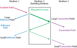
Figure 1 Schellkunoff model of E-field shielding. Source: York EMC Services.
Shielding effectiveness of microwave cable assemblies: Why is it important? How does it impact system performance? What makes a “good shield” good and a “bad shield” bad? In this article, we will examine cable assembly construction and show an example of the shielding effectiveness of airframe cable assemblies.
Before delving into shielding effectiveness, let’s define the term. A shield is a conductive barrier that envelops and isolates an electrical circuit. For a microwave coaxial cable, the isolated electrical circuit is the center conductor, dielectric and outer conductor. Because of the skin effect, at microwave frequencies the return current on the outer conductor travels through a thin layer of the inner diameter of the outer conductor. This leaves the remaining portion of the outer conductor as the shield. Shielding effectiveness is defined as the ratio of the RF energy incident on one side of the shield to the RF energy transmitted to the opposite side.
Reflection and absorption are the two primary shielding mechanisms. A widely-accepted analytical representation of shielding, known as the Schellkunoff Model,1 is illustrated in Figure 1, where Medium 2 is the shield. A portion of the incident RF energy is reflected from the surface of Medium 2. The remaining portion of the energy penetrates Medium 2, and a portion of it is absorbed, with its power dissipated by the ohmic losses in the material. The remaining energy propagates through Medium 2 to Medium 3, where a portion is reflected and the remaining energy moves into Medium 3, which is the region intended to be isolated by the shield.
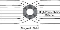
Figure 2 Magnetic field shielding.
The majority of shield configurations only protect against E-field radiation. Magnetic field protection requires a different approach. As there is no practical means to block the magnetic field, it must be redirected around the electronic circuit by housing the circuit in a material having high magnetic permeability (see Figure 2). The high permeability material, illustrated as a ring in the figure, distorts the magnetic field and isolates the center of the ring. This type of shielding is often employed when high energy, electromagnetic pulse exposure is anticipated.
SHIELD CONSTRUCTION
Microwave coaxial cable shields can take a number of forms. By far, the simplest and most effective shield is the outer conductor of a semi-rigid coaxial cable. The semi-rigid’s construction employs a relatively thick, one-piece cylindrical outer conductor, formed from high conductivity material. This endows it with excellent shielding effectiveness, well in excess of 140 dB from 1 to 18 GHz.
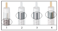
Figure 3 Common microwave cable shield configurations. Source: Emerson Corp.
Figure 3 shows four common shield types for flexible microwave cables. Type 1 is a braided round-wire shield, usually tin or silver-plated copper, and the most prevalent. This construction is highly flexible, easy to manufacture and serves a dual role as both a structural and electrical member. Its disadvantage is that the shielding effectiveness is directly proportional to braid coverage. With standard coverage, the typical shielding effectiveness is 40 dB through 18 GHz. Higher braid coverage will improve the shielding at the expense of cable flexibility, longer manufacturing times and increased material costs.
A braided, flat-wire shield (type 2 in Figure 3) is generally silver-plated copper. This type is structurally strong, has better shielding than type 1—typically 85 dB through 18 GHz—and the application time in manufacturing is short. However, it has higher contact resistance compared to a helically-wrapped, flat-wire shield and lower phase and amplitude stability with flexure. The helically-wrapped, flat-wire shield (type 3) improves phase and amplitude stability with flexure, reduces contact resistance, is highly flexible and can achieve a shielding effectiveness of 120 dB through 18 GHz. High quality cables use silver-plated copper flat wire. However, applying the shield is demanding, and the application process is slower than that of type 1 and 2 shields, raising the overall cost.
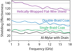
Figure 4 Shielding effectiveness of the most common shield configurations.
The fourth common shield construction (type 4) uses helically-wrapped, or “cigarette wrapped,” metalized polymer foil, using Mylar®, polyimide or polyester. Polyimide offers high strength and chemical and heat resistance. Aluminum-polyester Mylar is inexpensive, light-weight and provides electrostatic discharge protection. The downside is lower performance shielding, requiring metal deposition to be conductive. The deposition process results in somewhat high contact resistance, which hurts shielding effectiveness and usually requires a “drain wire” to provide a low resistance ground path. The shielding effectiveness of the most common types of shields are compared in Figure 4.