
To demonstrate additional benefits of this DGS design approach, assume that excellent rejection is needed at 8.4 GHz. To achieve that performance in the LPF, during the modeling phase of the project, a simple microstrip transmission line is simulated with a specially designed ground opening on copper layer 2 as a DGS; the intent is to achieve a broadband bandstop function at 8.4 GHz. The model is optimized for the best return loss over the LPF’s passband, from DC to 2.2 GHz. For improved isolation at 8.4 GHz, the circuit of Figure 4 is included in the final DGS LPF design in the area of the filter’s 50 Ω feedline. Figure 5 shows how these circuit features combine to form the final DGS LPF design.
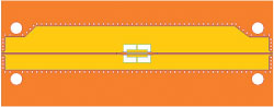
Figure 4 Prototype microstrip transmission line with an optimized DGS bandstop feature to provide good passband return loss and high rejection at 8.4 GHz.

Figure 5 Final microstrip DGS LPF circuit design, including the transmission line structure for enhanced rejection at 8.4 GHz.
PERFORMANCE
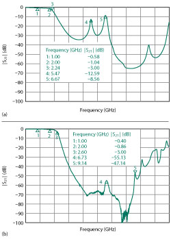
Figure 6 |S21| of the circuits in Figure 3a without a DGS (a) and LPF in Figure 5 (b).
Figure 6 shows |S21| responses of the LPF circuit without DGS features (see Figure 6a) and with DGS features (see Figure 6b). Comparing the filter responses, note that the filter circuit with DGS was not optimized to achieve the 3 dB cutoff frequency design goal. The 3 dB cutoff frequency for the reference filter circuit (i.e., the circuit with no DGS) is 2.243 GHz (marker 3 in Figure 6a), while the 3 dB cutoff frequency for the filter circuit with DGS is 2.604 GHz (marker 3 in the Figure 6b).
Comparing the |S21| responses of the filters, the most notable differences occur in the stopband beyond the 3 dB cutoff points. For the circuit without the DGS, markers 4 and 5 indicate frequencies where unwanted resonances are causing poor stopband performance. Marker 4 is at a resonant peak associated with the middle section of the high-impedance conductor, and marker 5 is a spurious harmonic at approximately 3f0, where f0 is the 3 dB cutoff frequency. The resonance at marker 4, which is at approximately 5.47 GHz, is due to the high-impedance, narrow conductor in the middle of the circuit, which has a physical length of nearly λ/2 at 5.47 GHz, causing a standing-wave resonance for that wavelength and frequency. For the LPF circuit containing the DGS, the high-impedance sections are physically shorter and the wavelength is different in that area because the conductor experiences a thicker substrate which has a relative permittivity of the combined materials (εr1 of 6.4 and εr2 of 2.9). Additionally, the DGS openings produce a slow-wave effect, which allows the circuit features to be shorter. Due to these differences, the λ/2 resonance at 5.47 GHz is eliminated with the DGS structure.
Having a spurious harmonic at 3f0 is a natural byproduct of a microstrip stepped-impedance filter. It is well known that this spurious harmonic can be significantly suppressed if the high-low impedances of the stepped-impedance circuit features have a wider range. Marker 5 at 3f0 (6.671 GHz) for the circuit without the DGS shows a loss response of 8.6 dB, where the circuit with the DGS (marker 4 at 3f0) shows a loss response of 55.1 dB. Also note the stopband improvement at 8.4 GHz with the filter having the DGS. High losses of almost 90 dB are shown between markers 4 and 5, in the vicinity of 8.4 GHz.
References
- S. K. Parui and S. Das, “A New Defected Ground Structure for Different Microstrip Circuit Applications,” Radioengineering, Vol. 16, No. 1, April 2007, pp. 16–22.
- L. H. Weng, Y. C. Guo, X. W. Shi and X. Q. Chen, “An Overview on Defected Ground Structure,” Progress in Electromagnetics Research B, Vol. 7, 2008, pp. 173–189.
- M. K. Mandal and S. Sanyal, “A Novel Defected Ground Structure for Planar Circuits,” IEEE Microwave and Wireless Components Letters, Vol. 16, No. 2, February 2006, pp. 93–95.
- J. Coonrod, “Harmonic Suppression of Edge Coupled Filters Using Composite Substrates,” Microwave Journal, Vol. 55, No. 9, September 2012.
- J. Coonrod, “Applied Methodology for Harmonic Suppression of Microstrip Edge Coupled Bandpass Filters Using Composite Circuit Materials,” European Microwave Week, September 2015.