Electronically Tunable RF Filters for LMDS Frequencies
Paratek Microwave Inc.
Columbia, MD
Local multipoint distribution service (LMDS) is a two-way digital wireless communication medium enabling voice, data and video traffic. LMDS applications are located in the 22 to 40 GHz range of the spectrum and provide an attractive solution to the last-mile problem of connecting consumers to broadband communication services such as high speed Internet and video without the limitations of copper lines and the prohibitive installation costs of fiber.
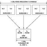
 The radios currently used at LMDS frequencies utilize fixed filters. An electronically tunable RF (ETRF) filter has been developed that covers the frequency range for several fixed filters. ETRF filters provide fast tuning, maintain high Q values at LMDS frequencies and enable a single radio to operate at multiple frequencies. These attributes equip LMDS service providers with flexibility and scalability by enabling software control, frequency reuse, coexistence with adjacent systems and performance optimization. Figure 1 shows a comparison of fixed-filter technology operating within a typical frequency range of 1 GHz and the ETRF filter solution. Multiple sets of fixed-frequency duplexers can be replaced by one set of ETRF filters.
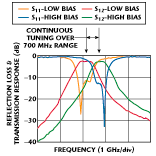
 The new ETRF filter products represent the first commercially available high frequency, low loss, wideband electronically tunable filters of their kind. The typical performance of an ETRF Ka-band filter for LMDS applications is shown in Figure 2 . The example bandpass filter is a two-pole Chebyshev finline waveguide design, which utilizes the company s proprietary ceramic planar varactors. By applying DC voltage to the varactors, fast tuning of the capacitance is achieved. The filter features low loss and fast tuning performance over approximately a 700 MHz tuning range, and offers a 1 dB relative bandwidth of 2.8 percent, tuning range of more than 3.2 percent of the center frequency and insertion loss of 2 dB. The filter exhibits high power handling with low DC power consumption and also features low intermodulation distortion of > 70 dBm.
|
Table 1 | |
|
Frequency range (GHz) |
22 to 40 |
|
Tuning range (% of fo ) |
2 to 5 |
|
Bandwidth (MHz) |
200 to 50 |
|
Insertion loss (dB) |
2.0 |
|
Poles |
2 to 4 |
Units are available in metal or metallized-plastic housings with a standard waveguide interface. The operating temperature range is -30º to +70ºC, and the filter measures a compact 0.875" x 0.875" x 0.750" (excluding the bias port). Table 1 lists the range of ETRF filter specifications at LMDS frequencies. Digitally controlled options are available. Additional information on ETRF filters for LMDS applications and other ETRF products such as tunable delay lines, phase shifters and electronically steerable antennas can be obtained from the company s Web site at www.paratek.com or via e-mail: info@paratek.com.
Paratek Microwave Inc., Columbia, MD (443) 259-0140.
