
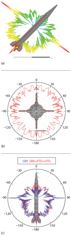
Figure 1 RCS of an 11.5 m × 2 m × 2 m missile at 10 GHz: co-polarization response with the missile (a), co-polarization axial cut (b) and co-polarization SBR compared to SBR+PTD+UTD.
ANSYS HFSS 19.0 features a significant new capability to model the radar signatures of electrically large targets and scenes with the integration of HFSS SBR+. Shooting and bouncing rays (SBR) is a ray tracing technique within the physical optics (PO) framework and is suitable for efficiently solving electromagnetic (EM) problems that are hundreds and thousands of wavelengths in size. Integration of HFSS SBR+ to the available high frequency EM solver technologies in ANSYS Electronics Desktop allows radar designers to apply the best analysis technologies for predicting the radar signatures of structures ranging from sub-wavelength to kilo-wavelengths.
With ANSYS 19.0, existing HFSS customers can use the SBR+ solver in addition to the time-tested flagship HFSS finite element method (FEM) and integral equation (IE) solvers. Empowered by advanced diffraction physics from the physical theory of diffraction (PTD) and uniform theory of diffraction (UTD), HFSS SBR+ provides accurate and efficient large-scale EM modeling for structures containing metals and dielectrics, as well as structures with dielectric losses, multi-layer dielectrics and absorbing materials. ANSYS now provides a single framework for all high frequency EM solvers, facilitating a smooth and unified workflow to solve these complex EM problems. For radar signature analyses, HFSS SBR+ features monostatic and bistatic radar cross-section (RCS) modeling capabilities with the implementation of plane wave excitations.
Efficient modeling of RCS in ANSYS HFSS SBR+ can help determine and control the radar signature characteristics of commercial and military platforms, such as aircraft, ships, ballistic missiles, submarines, ground vehicles and satellites. Taking RCS measurements on full vehicles is a costly and time-consuming process; simulation cuts down on prototype measurements and shortens vehicle concept design cycles. RCS reduction of large aircraft, vessels and missiles is critical in radar stealth technology, to reduce detection probability; simulation is essential in this endeavor, as RCS data obtained through simulation can predict detection. Simulation can also help develop specifications for radars, to detect commercial maritime shipping vehicles and determine methods to mitigate radar clutter in air traffic control radars caused by wind turbines. ANSYS Electronics Desktop provides features for target model building, computer-aided design (CAD) import and healing, simulation, distributed computing and post-processing.
These simulation technologies can be dramatically quickened through ANSYS high performance computing (HPC), using multi-core parallel processing and graphics processing unit (GPU) acceleration on both high-end GPU appliances and consumer video graphics adapters. With this highly efficient solution, ANSYS HFSS SBR+ users can simulate across many design variations to thoroughly study and optimize the complex radar signatures of large vehicles.
To illustrate, consider the RCS analysis of a missile in ANSYS Electronics Desktop, shown in Figure 1. The results show the monostatic RCS of a missile with an electrical size of 385 λ × 70 λ × 70 λ, comparing the monostatic RCS solutions obtained from the standard SBR with results from the SBR solver with PTD and UTD. The addition of the extended physics for SBR+ reveals a larger response for the monostatic RCS in some regions, notably near the front of the missile. Even with the extended physics applied, the simulations were fast and extremely efficient. The standalone SBR simulation required just nine minutes on a quad-core computer with 0.075 GB RAM. As the results in Figure 1(c) indicate, advanced diffraction physics is important for accurate results at nose-on angles.
A second example shows the bistatic RCS of a shipping vessel analyzed at 1 GHz with a plane wave incident at θ = ‐45 degrees and φ = ‐45 degrees (see Figure 2). The vessel was modeled in isolation, then compared to a second simulation with a finite extent of sea water. To account for reflections from the water surface, a 400 m × 400 m seawater surface was modeled with appropriate lossy material properties. This electrically large problem of 1333 λ × 1333 λ was solved in ANSYS HFSS SBR+ in just 86 seconds on a quad-core computer, requiring only 0.5 GB RAM.
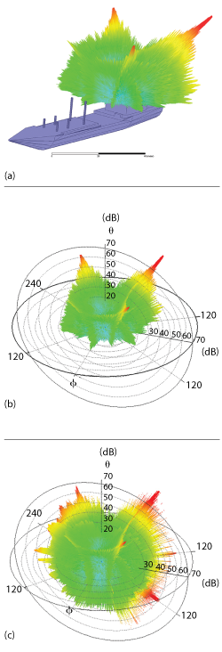
Figure 2 Bistatic RCS of a 104.6 m × 16 m × 18.5 m ship at 1 GHz (a). The RCS of the isolated ship (b) vs. the ship with seawater (c).
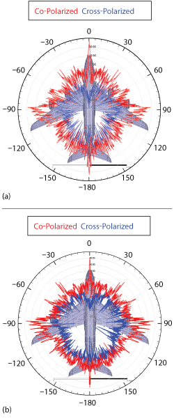
Figure 3 Simulated co-polarized and cross-polarized RCS for an Airbus 380 aircraft 79.62 m × 72.84 m × 21.62 m at 2.8 GHz (a) and 10 GHz (b).
A final example shows the RCS of an Airbus 380 aircraft at 2.8 and 10 GHz, and the co-polarized and cross-polarized monostatic RCS responses are shown in Figure 3. At 2.8 GHz, the 743 λ × 680 λ × 202 λ structure was solved in two hours using 0.1 GB RAM. At 10 GHz, the electrical size was 2,654 λ × 2,428 λ × 721 λ.
The addition of HFSS SBR+ solver to the portfolio means HFSS users can extend the frequency range for analyzing the radar signatures of their designs. The flow is highly automated and tightly integrated into the same Electronics Desktop as HFSS, meaning current users will have an easy time adopting this new solver technology into the simulation flow. HFSS SBR+ can be a key contributing tool in any design flow where stealth and radar signature analysis of structures with large electrical size and at very high frequencies is a critical performance metric of the system.
ANSYS
Canonsburg, Pa.
www.ansys.com