

The need for speed and ubiquitous connectivity is a major driver behind today’s revolution in MHz to THz technologies. Barely a decade ago, who would have guessed that the world would be trying to connect billions of devices on the Internet and preparing to download a movie in a few seconds to a smartphone? Wireless applications have evolved from point-to-point to broadcast systems to mesh and cellular networks, and now systems with directive networks combining point-to-point and cellular systems are being explored.
mmWave frequencies refer to the electromagnetic spectrum with wavelengths between 1 to 10 mm representing the frequency range between 30 and 300 GHz. There are many innovative applications of mmWave technology being implemented today including telecommunications, wireless communications, automotive, aerospace and defense, imaging, security, medical and other industrial applications. However, in the context of wireless communication and automotive radar sensors, the two fastest growing applications, mmWaves are generally referred to as multiple bands of spectrum in the frequency range of 24 to 86 GHz. This article is focused on the technology and major applications in this frequency range.
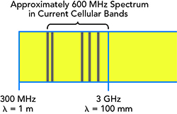
Figure 1 Frequency bands available for wireless communications in the U.S.
The mmWave spectrum has many advantages when compared with lower frequencies, as it is congestion free and has the capacity to move data at speeds of up to 10 Gbps and beyond. Due to its short range, frequency re-use is a big advantage in many use cases. Smaller size components, and particularly antennas, are also an advantage. On the negative side, the transmission distance is typically less than lower frequencies due to higher propagation loss and, presently, is higher in cost.
Growth Expectations
The mmWave technology market is expected to grow 10x in the next five years to more than $4 billion.1 The growth of this market is being propelled by the growth in mobile data traffic and higher usage in small cell backhaul networks. Telecommunications are one of the largest markets for mmWave technology because they have been widely used in small cell backhaul networks. The mmWave backhaul equipment is used as an integral part of the LTE/4G deployments. For 5G, the aggregate data rates are expected to be 1000x more than that of the existing 4G data rates; thus, there will be an even greater need for the mmWave spectrum to provide desired data rates. Over the frequency range from 24 to 86 GHz, the potential bandwidth available is about 20 GHz compared to less than 1 GHz bandwidth available in frequency spectrum below 6 GHz. This opens the door to a huge data carrying opportunity (see Figure 1).
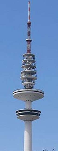
Figure 2 Microwave Tower, Hamburg, Germany. Photo Credit: Kristof Hamann
mmWave growth in commercial markets started with the need for cellular backhaul in the early 1990s. Long range radio relay links at lower frequencies (1 to 18 GHz) were in use for quite some time, but the need for higher frequency, shorter distance links were necessary with the fast-developing cellular infrastructure. These point-to-point radios used licensed bands of 23, 26 and 38 GHz (see Figure 2). The range for these radios is less than 10 km and enabled the building of worldwide cell phone infrastructure during rapid deployment phases. These developments happened when RF technology developments were going through an evolution to increased use of MMICs. Higher frequencies were added more recently including unlicensed 57 to 64 GHz band and lightly licensed bands of 71 to 76 and 81 to 86 GHz offering higher bandwidths, increased capacities, smaller size but shorter range. All these bands are presently being used for digital radio links for point-to-point links within and outside the cell phone infrastructure providing multiple Gbps capacities. Fiber optical links are a big player in this application, but mmWave links provide faster implementation and lower cost. Additionally, in many locations fiber is not even an option due to challenging terrain or other issues.
Semiconductor Technology
Semiconductor technology development over the last two decades is largely responsible for enabling the mmWaves to meet the growing demand for speed, bandwidth and connectivity. The III-V semiconductors have been carrying the load, with GaAs being the first to support mmWave MMIC functions. It continues to be important for providing individual circuit functions but GaN has become a significant player for broadband power applications. InP HEMT/mHEMT are commonly used for low noise niche applications at ultra-high frequencies. InP HBTs also perform well at high frequencies with sufficient breakdown voltages and moderate integration capability. Figures 3 and 4 show examples of a high performance mmWave power amplifier and low noise amplifier MMICs operating in the 50 to 100 GHz band. Recent developments of integrated mmWave transmitters and receivers and new phased array and beamforming techniques are paving the way for the mmWave communications like they did in the military for radar systems.
Operation at mmWave frequencies at reasonable costs is largely the result of the advancements in CMOS and SiGe technologies. Packaging the analog components needed to generate mmWave RF signals, along with the digital hardware necessary to process massive bandwidths, has only been possible in the last decade. Today, transistors made with CMOS and SiGe are fast enough to operate into the range of hundreds of GHz, as shown in Table 1. The SiGe HBT is presently being used in many applications as it is fast and provides high integration, but has low breakdown voltages, which can be overcome by stacking in many cases.
Inexpensive circuit production processes are making system-on-chip (SoC) mmWave radios possible—a complete integration of all analog and digital radio components onto a single chip. For mmWave communication, the semiconductor industry is ready to produce cost-effective, mass-market products. For demanding applications requiring highly customized performance and low volumes, thin film hybrid technology using ceramic/quartz substrates for filters/power distribution circuits and mmWave MMICs are used in shielded metal housings. These applications include test equipment, satellite communications, back-haul radios and mil-aero applications. Figure 5 shows an E-Band transceiver (without lid) using ceramic substrates and mmWave MMICs.
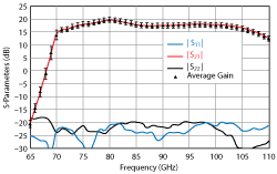
Figure 3 HRL GaN power amplifier MMIC 70 to 105 GHz BAL-WPA.
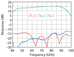
Figure 4 Analog Devices LNA MMIC GaAs PHEMT 50 to 95 GHz.
Automotive Radars
History
Research and development of automotive radars started in the 1970s. Different frequency radars were tested, and in 1989, the World Administrative Radio Conference (WARC) settled on 77 GHz band for this application. It was not until 1998 that a commercial product at 77 GHz was implemented by Mercedes.2 In 2006, 24 GHz radars were introduced for shorter range applications. While 77 GHz radar was used for obstacle detection and automatic cruise control (ACC), 24 GHz was used for blind spot detection and lane departure warning. A timeline showing the evolution of the automotive radar is shown in Figure 6. As per the National Highway Traffic Safety Administration, 20 U.S. automakers made an agreement last year that all new cars produced starting in September 1, 2022 will be outfitted with automatic emergency braking (AEB) systems.3 Millions of cars on the road today are already outfitted with radar sensors, as the cost has dropped over the years.
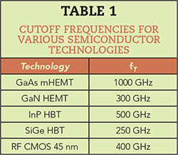
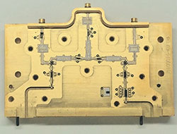
Figure 5 E-Band transceiver (courtesy National Instruments).
Automotive radar is a key sensor of advanced driver assistance systems (ADAS). Other sensors include light detection and ranging (LiDAR), ultrasonic sensors and camera vision systems. Compared to radar, a LiDAR today offers higher resolution and can build a 3D image of the target. However, it is very expensive and offers limited use in bad weather and at night, plus it covers a shorter range. Figure 7 shows a typical ADAS system consisting of various types of sensors.

Figure 6 Timeline of automotive radar history.
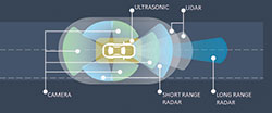
Figure 7 Advanced Driver Assistance System sensors.
The rapid evolution of ADAS is paving the path to fully autonomous vehicles. At one time, ADAS systems, or parts thereof, were the domain of high-end luxury cars. But now, thanks to technology evolution and reduced costs, they are finding their way into mid-range and economy vehicles. Consumer demand for ADAS is high, and governments worldwide are considering benefits of passing laws to make such systems standard equipment in all vehicles. The need for radar sensors is supported by studies that have shown a significant reduction in fatal accidents by using ADAS systems. According to the World Health Organization, more than one million people die every year in traffic accidents. Once ADAS systems are implemented, this number is expected to decline more than 50 percent.
In order to reduce costs and size, automakers would like to integrate multiple ADAS functions onto a single platform that handles data from multiple sensor types. This “sensor fusion,” representing the combination of data derived from different sensors, results in a higher level of accuracy and is more comprehensive than would be possible if the sensors were used individually. Fusion sensors, particularly ones combining radar chips and image sensors (cameras), are now becoming available.
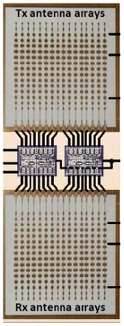
Figure 8 SiGe BiCMOS 8Tx/8Rx chip. (Courtesy Gabriel Rebeiz, UCSD)
Radar Technology
Automotive radars for ACC and collision avoidance operate over 76 to 77 GHz and are used for Long Range Radar (LRR) up to 300 m, with typical bandwidths between 400 MHz and 1 GHz. Using a linear FMCW modulation, these sensors provide resolution of about 0.5 m. Until 2010, GaAs PHEMT was the technology typically used for these frequencies. As the technology matured and volumes increased, SiGe MMICs took over as the technology of choice. Presently, RF CMOS using 45 nm or FD SOI 22 nm has advanced to cover this frequency range and is expected to take the lead because of cost advantages and the potential for higher levels of integration.
A new frequency band 76 to 81 GHz has been approved in many countries and is expected to become the long-term solution for automotive radar sensors globally. Using 4 GHz of bandwidth, it has the potential to achieve resolution better than 10 cm. As an example, Figure 8 shows a 75 to 85 GHz, 8Tx/8Rx chip with up/down‐converter and built-in self-test (BIST) for automotive radar applications. It was made with the GF8HP 0.12 μm SiGe BiCMOS process (200 GHz fT) and has an area of 26 mm.2 Receiver gain is 24 dB at 77 GHz and Tx to Rx coupling is an impressive 52 dBc.4 Over the last few years, several semiconductor companies have released high performance and small size 77 GHz ICs that enable potential use of multiple radar sensors in a car to provide high resolution 360 degrees coverage. Multi-channel ICs providing electronic scanning are also available.
The 24 GHz radar sensor covers 24 to 24.25 GHz and is used as Short Range Radar (SRR) for distances to 50 m. It is commonly used for parking aid, blind spot detection and lane change assist. Using linear FMCW modulation, range resolution of 1.5 m can be achieved. Highly integrated transceiver MMICs based on 0.18 μm SiGe technology are commercially available. Millions of 24 GHz sensors are in operation presently and are also used in industrial sensing. It is important to note that in Europe, there is a sunset date in 2018, meaning no new cars will be fitted with these sensors there. This assumes that 76 to 81 GHz sensors will be fully deployed by that time and will cover both SRR and LRR applications.
Test Challenges
Testing vehicular radar sensors involves target simulation as well as measurement of key RF parameters. Until recently, testing for target distance, speed, angle and size was accomplished in a field using physical obstacles and moving vehicles. With the increasing volumes and technology advancements, it has become possible to simulate the targets and take measurements of EIRP, spectral occupancy, phase noise, antenna beamwidth and chirp analysis. An example is shown in Figure 9 of the National Instruments’ Vehicular Radar Test System. A 76 to 77 GHz signal from the radar sensor is received and down-converted to C-Band before feeding a vector signal transceiver (VST) that measures desired parameters. Beamwidth is measured by placing the radar on a calibrated rotor, and signal strength is measured as a function of angle. This will become even more important for autonomous driving as it is difficult to test all the physical scenarios in the field.
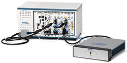
Figure 9 77 GHz Auto Radar test front-end (courtesy National Instruments).
Simulation of a target includes simulating distance, speed, angle and size of the target. A down-converted signal uses a hybrid method of passive and active approaches to simulate targets covering the full distance range of 3 to 300 m. Active simulation uses the VST to simulate targets with the help of LabVIEW FPGA-based signal processing. Target distance is simulated by delay, speed (Doppler) by Tx-Rx frequency offset and target size (RCS) by controlling power level. The VST also has capability of adding multiple targets. This system was demonstrated by Konrad at NIWeek 2017.5
Future Directions
There is a high level of activity to develop radar sensor ICs which can provide 4 GHz bandwidth (77 to 81 GHz) to achieve finer resolution. A combination of high resolution based on wide bandwidth and micro-Doppler techniques will provide enhanced performance. 3D imaging radars are gaining interest in the framework of ADAS, and synthetic aperture radar techniques are being investigated for use in automotive radar applications. In terms of modulation schemes, linear FMCW slow single carrier is being replaced by fast chirp single carrier. Advanced modulations like fast chirp FDM and OFDM PCM will be implemented in a phased manner. Frequencies higher than 77 GHz are also being explored for future use.
While ADAS is the enabler for autonomous vehicles, there are other technologies which will need to be integrated to arrive at autonomous vehicles, including vehicle to vehicle (V2V) networking, in-car networking, vehicle to everything (V2X) and satellite navigation. The autonomous vehicle technology has the potential of not only dramatically reducing road fatalities, but also providing a new transportation for the disabled and those who are too old or too young to drive. Governments all over the world are interested in enabling necessary regulations, but there are certainly challenges to overcome. In the U.S., 18 states have passed regulations to allow autonomous vehicles on the roads under certain conditions.
5G
The exponential growth of connected “things” and the capacity necessary for intercommunication are fueling the need for speed in wireless communications. From just a few billion “things” connected five years ago, we have already crossed 10 billion devices including hand-held smart devices.6 This number is expected to double in three years and is expected to continue increasing rapidly due to explosion of the Internet of Things (IoT). Everything from smart homes, cities, cars, pets, sensors, etc. are being connected. Industries including health, energy and transportation are expected to go through an unforeseen revolution due to intercommunication of people and things. The combination of need for high bandwidth data capacity, low latency and an exponential number of connected devices has researchers investigating access networks operating above 6 GHz. Frequencies below 6 GHz have wide area coverage when compared with higher frequencies, and while innovative techniques will be put into action to make more efficient use of this already allocated spectrum, there is a growing need to look for new spectrum bands for 5G that are above 6 GHz.
There are several deployment scenarios for mmWaves as part of 5G access network. These include high capacity backhaul point-to-point radio links, point-to-multipoint Fixed Wireless Access (FWA) and cellular access. Backhaul mmWave applications have provided a commendable service for the 2G, 3G and 4G infrastructure. Commonly used licensed frequency bands include 23, 26, 38 and 60 GHz. 5G deployments are expected to use upgraded links to handle increased data capacities.
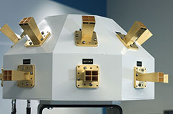
Figure 10 28 GHz Channel sounder by AT&T and National Instruments (courtesy National Instruments).
While the use of mmWave frequencies is assured in backhaul and FWA, efforts are still on the way to enable its use in cellular access. In order to evaluate the radio environment for mmWaves communication, especially the systems with multiple antennae, channel sounding efforts were started in the last decade. Many research organizations have been studying and experimenting at different frequency bands all over the world. At NIWeek 2015, Nokia and National Instruments demonstrated a 2 x 2 MIMO system at 73 GHz using 2 GHz bandwidth, which provided a 10 Gb/s link over 200 m with better than 1 msec latency.7 National Instruments also partnered with AT&T to develop a 5G mmWave channel measurement tool. The channel sounder provides real-time channel parameter measurement and monitoring capability. The channel sounder was designed by AT&T and uses an architecture based on National Instruments’ 28 GHz Transceiver System shown in Figure 10. This channel sounder captures channel measurements where all the data is acquired and processed in real-time with the capability to take about 6000 measurements in 15 minutes.8
The small size of antennas at mmWave frequencies enables the use of multiple antennas in phased arrays and MIMO systems more effectively. MIMO allows a communications system to use spectrum more efficiently by employing spatial multiplexing and beamforming. With spatial multiplexing, a base station uses multiple transmit antennas to beam distinct streams of information to multiple users at the same time using the same spectrum. Now 5G researchers are looking to massively increase the number of spatial streams used in a mobile communications system. Eventually, the 5Ms (mmWave massive mimo) are expected to enable the peak performance of these 5G systems. Hybrid beamforming and MIMO systems will provide significantly increased speeds using directive beam configurations compared to previous omni-directional radiations.
Several different frequency bands between 24 and 86 GHz are being considered for this application, with 28 and 39 GHz currently being developed for FWA. The final decision for approved frequency bands for mobility will be taken at the WRC19 meeting of ITU in November 2019. Figure 11 shows various bands available for 5G in different parts of the world.
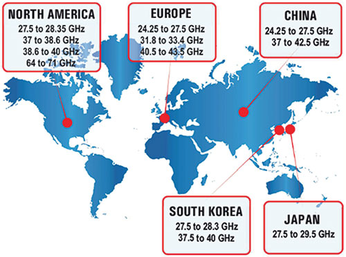
Figure 11 Frequency bands available for 5G.
Fast Wi-Fi
Wireless Internet implementation started about 20 years ago using the 2.4 GHz frequency band. Wi-Fi standards have so far been limited to 2.4 and 5.8 GHz; however, the performance over time has slowly evolved through 802.11 a/b/g/n/ and more recently, 802.11ac. These standards can effectively cover a large home or estate, using recently released systems with multiple routers as mesh networks. These links have capability to provide data rates of several hundreds of Mbps. The next standard in the series, 802.11ax, is based on multi-user MIMO and is expected to provide more than a Gbps data rates soon.
On the other hand, 802.11ad is a fast lane Wi-Fi system, operating on an unlicensed 57 to 64 GHz band, that is separate from present Wi-Fi standards in use. Using a maximum of 2.16 GHz of bandwidth, it is designed to support data rates up to 7 Gbps. Using a new mmWave frequency band that has limited range reduces interference. 802.11ad covers about 10 m, effectively making it best suited for in-room activities such as: wireless docking station, streaming from a smart device to a smart TV or Chromecast, transferring heavy media files such as 4K footage or raw images and certain gaming applications. This capability is showing up in laptops but has not yet entered the smartphone market.
802.11ay, an extension of the 802.11ad based on channel bonding and MU-MIMO, is in development and is expected to be ready by the end of the year. This standard is expected to ramp up transmission rates from the current 7 Gbps to about 30 to 40 Gbps, and to extend transmission distance from the current 10 m to as far as 300 m. 802.11ay will use 57 to 70 GHz and bond four of 802.11ad channels together for a maximum bandwidth of 8.64 GHz. 802.11ay applications potentially include replacements for Ethernet and other cables within offices or homes, as well as provide backhaul connectivity outside for service providers. The limitation of practical speeds achieved will shift to the infrastructure and ISPs, which will have a harder time keeping up with the new Wi-Fi standards. It is obvious that mmWaves are bound to play a significant role in future Wi-Fi systems requiring moving large amounts of data. Figure 12 shows frequency bands for the three key mmWave applications discussed.

Figure 12 Frequency bands available in the U.S. for the three major mmWave applications.
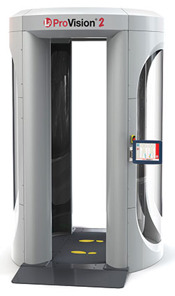
Figure 13 Millimeter Wave full body scanner by L-3.
Security Applications
mmWaves are used in various security functions, from wireless fences to intruder sensors to safe full body scanners. Over the last 10 years, mmWave scanners have gradually replaced metal detectors at U.S. airports. These scanners have the capability of detecting metal and non-metal objects on the body, and due to their low power operation, represent a safe scanning method. The mmWave safety standards are power density based and expressed in mW/m2. The power density for a mmWave scan is between 0.00001 and 0.0006 mW/cm2.9 This type of scanning is thousands of times less than what is permitted for a cell phone. Unlike X-ray scanners, they emit non-ionizing radiation that does not cause cell damage that could result in cancer. Operating between 24 and 30 GHz, mmWave scanners use multiple antenna arrays to transmit and receive high frequency radio waves as they scan the person. The raw data is turned into a hologram that is examined for suspicious objects by algorithms. The holograms are then rendered into 3D figures for inspection. The entire process takes six to eight seconds. For privacy reasons, the algorithms used convert the 3D image to a generic outline of the human body on the computer screen. Presently, mmWave scanners are being used in hundreds of locations in the U.S. and Europe. Figure 13 shows a commonly used mmWave scanner by L-3.
Last year, Rohde & Schwarz introduced a mmWave security scanner operating in the 70 to 80 GHz frequency range that automatically detects potentially dangerous items carried on the body or in clothing. This scanner is being deployed at many airports across Europe for airport security checks. This scanner transmits about 0 dBm power, has an impressive data acquisition time of 32 msec and uses fully electronic scanning.
Medical Applications
mmWaves have shown a great promise for medical applications—continuous wireless monitoring of breathing and heart rate is one of them. Using coherent radar systems, phase shifts associated with small displacements in a human body can be accurately measured. These micro-Doppler features can be used to determine biometric information related to respiration, heartbeats and other subtle motions of the body. This non-contact, remote technique can provide information related to a person’s physiological and medical condition. This is useful in maintaining health and timely detection of many health issues. This can enable hospitals to unwire patients who need continuous monitoring.
Many frequencies have been used, including 60, 94 and 228 GHz. In one system by UC Davis using 60 GHz, the mmWave signals were directed to the body and the reflected signal was analyzed for an accurate estimation of breathing and heart rates. Directional beams of mmWave are also used to monitor multiple humans in an indoor space, and can be used to locate individual humans in the room as well. Researchers can measure breathing rates with a mean estimation error of 0.43 bpm and 2 bpm in heart rates. Therefore, the system can locate the human subjects with 98 percent accuracy and is effective in monitoring multiple people in parallel, even behind walls. In another application, a 228 GHz heterodyne radar system has been used to measure respiration and heart rates simultaneously, at distances of up to 10 m. A key advantage to higher frequency systems is the ability to focus the beam and illuminate one subject at these distances, thus reducing clutter and the complexity of the signal.10
mmWave imaging can also be used for noninvasive diagnosis, with one of the applications being skin burn injuries. Using 26.5 to 40 GHz, it has been shown that the degree of skin burns can be diagnosed and the healing process monitored without opening the wound. This technique takes advantage of the fact that reflection properties of the healthy tissue are very different from the drier, burned tissue. Similar approaches have been used for diagnosing skin cancer and breast cancer. The dielectric constant of the tumor tissue is approximately 5x greater than that of fat. In one case, a 30 GHz signal with a bandwidth of 20 GHz was used and the reflected signal was analyzed using stepped frequency continuous wave modulation.11 Wide bandwidth enables high resolution, while the choice of frequency provides adequate penetration in the human tissues for breast imaging applications. The experimental results obtained by employing the prototype in a real scenario show a cross resolution down to 3 mm, with a range resolution of 8 mm and a high dynamic range of about 60 dB by using 35 antennas. The results to date are promising, and they will serve as the baseline for the development of a full breast imaging system.
Conclusion
mmWaves have hit the road—the investments in developing the technology and products are finally paying off, and commercial applications are being released. Once an exotic technology, mmWaves are already used in several applications including short distance links, chip-to-chip connections on board, HDMI video from laptop to screen, fast Wi-Fi, wireless docking stations and automotive radars. Significant efforts are on the way in developing mmWave technology and bringing the cost down to enable continued growth of applications in the mil-aerospace, telecommunications, imaging, security, satellite communications and medical fields. The next decade is expected to see more applications and innovative products in the mmWave frequency ranges to 300 GHz.
Studies and experiments are in place to prove utility of this technology in the cell phone access field. Many propagation studies at 28, 38, 60 and 73 GHz have been carried out with encouraging results. Several challenges remain, and global harmonization of frequency bands needs to be achieved. Acceptance of mmWave bands for cell phone access will potentially provide the final push to get these tiny waves in the hands of billions of people in 5 to 10 years.n
References
- “mmWave Technology Market by Product, Frequency Band (V-Band & E-Band), Component, Application and Geography—Global Forecast to 2022,” marketsandmarkets.com, August 2016.
- H. H. Meinel and J. Dickmann, “Automotive Radar: From Its Origins to Future Directions,” Daimler AG, Stuttgart, Germany, Microwave Journal, September 13, 2013.
- “U.S. DOT and IIHS Announce Historic Commitment of 20 Automakers to Make Automatic Emergency Braking Standard on New Vehicles,” https://www.nhtsa.gov/press-releases/us-dot-and-iihs-announce-historic-commitment-20-automakers-make-automatic-emergency.
- Bon-Hyan Ku, Ozgur Inac, Michael Chang, Hyun-Ho Yang and Gabriel M. Rebeiz, “A High-Linearity 76 to 85 GHz 16-Element 8-Transmit/8-Receive Phased Array Chip with High Isolation and Flip-Chip Packaging,” IEEE T-MTT, October 2014.
- NIWeek 2017: https://www.youtube.com/watch?v=0MTkBlvEMHw&t=4s.
- A. Nordrum, “The Internet of Fewer Things—Early Predictions of 50 Billion Connected Devices By 2020 Are Being Scaled Back,” September 2016, http://spectrum.ieee.org/telecom/internet/the-internet-of-fewer-things.
- NIWeek 2015: https://www.youtube.com/watch?v=I5QwAxdiLmU.
- NIWeek 2017: https://www.youtube.com/watch?v=34EIDyRmb8Q&t=35s.
- J. E. Moulder, “Risks of Exposure to Ionizing and Millimeter-Wave Radiation from Airport Whole-Body Scanners” Radiation Research, 177 (6) (2012), pp. 723-726.
- Z. Yang et al., “Monitoring Vital Signs Using mmWaves,” University of California, Davis, Cailf., USA 17th ACM International Symposium, July 2016.
- S. Moscato et al. “A mmWave 2D Ultra-Wideband Imaging Radar for Breast Cancer Detection”, Department of Electrical, Computer and Biomedical Engineering, University of Pavia, International Journal of Antennas and Propagation, Vol. 2013.