
Electronic countermeasures or ECM systems are typically comprised of receivers, processors, displays and jamming transmitters. Until recently, solid-state amplifiers fell short of the required combination of power, bandwidth and efficiency for the transmitter of an ECM system. Maturating GaN power amplifier MMICs and low loss, broadband combining techniques now make it possible to meet the power, bandwidth and efficiency requirements of ECM systems with solid-state power amplifiers (SSPA). Compared to GaAs and other solid-state semiconductor materials, GaN provides an order-of-magnitude increase in transistor power density, and the higher impedance of the devices eases the design of matching networks.
Historically, traveling wave tubes (TWT) and other vacuum tubes have provided the microwave power for ECM transmitters. Since the 1950s, the broadband, high-power microwave amplification necessary for ECM transmitters was only feasible with vacuum tube technology and, in particular, with traveling wave tube amplifiers (TWTA). ECM jamming transmitters typically need to generate hundreds of watts of microwave power over several octaves. The efficiency of the amplifiers must be high enough to meet the limited power budget of airborne platforms and the heat generated can be dissipated. TWTAs were the only technology that could meet these critical requirements.
SOLID-STATE vs. TUBE
Solid-state devices have long been preferred to vacuum devices. Vacuum tubes, with their associated high voltage power supplies—typically in the multi-kV range—have lower reliability than solid-state devices operating with low voltage power supplies (i.e., under 50 V). Manufacturers and users of vacuum tubes face diminishing sources of supply and material shortages.
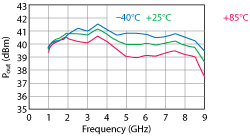
Figure 1 Output power vs. frequency and temperature of a Qorvo QPA1003P GaN MMIC, with 15 dBm CW input power, 28 V bias and 650 mA current consumption.
Solid-state devices generate lower noise and have better linearity than vacuum tubes. For instance, solid-state devices in “standby mode”—where the DC bias voltage is applied with no RF input signal—generate significantly less noise power across the spectrum. Noise figures for a medium power TWT can be around 30 dB, versus about 10 dB for a solid-state GaN MMIC PA. This is a significant difference in an ECM system, as the lower noise may allow the transmitter’s output stage to remain in standby mode when not transmitting. The overall switching time decreases, since the main DC power to the PA does not need to be switched on and off.
Another operational benefit of a solid-state transmitter is the reduced harmonic content in the output signal. A solid-state PA that operates over an octave or greater bandwidth will typically have worst-case harmonic content about 8 dB down from the fundamental at its saturated output power. The harmonic content of a vacuum tube will only be down 2 dB from the fundamental under the same operating conditions. These higher harmonics can impose stricter filtering requirements for the transmitter, driving larger and costlier components for the overall ECM system.
POWERING UP WITH GaN
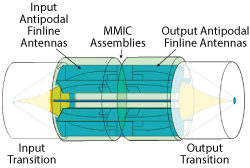
Figure 2 Spatium amplifier structure.
While GaN devices have significantly increased the power density, power and bandwidth over other heterojunction semiconductor technologies, a single device or MMIC still has insufficient power for most ECM system transmitters. It is not unusual to have a requirement of 100 W or more from 2 to 7.5 GHz. Figure 1 shows the output of a single Qorvo GaN power MMIC. This packaged MMIC nominally delivers 10 W from 1 to 8 GHz, but the output power decreases at 85°C backside temperature to as low as 8 W. More than 10 of these MMICs must be combined to deliver 100 W across the band and over the temperature range required in an ECM system.
There are many ways to power combine devices to make a SSPA. For an ECM system transmitter, the approach must have low loss and wide bandwidth. Many combining techniques use two-port binary combiners such as Wilkinson or magic tees. Combining two MMICs requires a single two-port combiner, four MMICs requires three combiners and 16-way combining requires 15 combining elements. Magic tees have relatively low loss; however, they typically operate over a maximum of 10 percent bandwidth, and double-ridged magic tees only have about an octave bandwidth, which is short of a 2 to 7.5 GHz ECM requirement. With two-way combining, four stages of combining are needed to achieve the desired power. A typical double-ridge magic tee has 0.3 dB of loss at these frequencies, so the total loss through the combiner would be 1.2 dB. Combining the 30 percent efficient GaN PA MMICs shown in Figure 1 through a 16-way magic tee, the efficiency of the combined output would be about 23 percent and deliver approximately 95 W output at 6 GHz at 85°C. However, the typical double-ridge magic tee network only works over an octave of bandwidth (e.g., from 2 to 4 GHz).
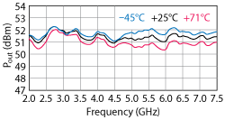
Figure 3 Measured output power of the Spatium amplifier that combines 16 QPA1003P MMICs.
SPATIAL COMBINING
Spatial combining techniques are potentially lower loss than circuit-based techniques. Spatium® is Qorvo’s patented coaxial spatial method of power combining (see Figure 2). It uses broadband antipodal finline antennas as the launch to and from the coaxial mode, splitting into multiple microstrip circuits, then combining the power from those circuits after amplification with a power MMIC. It uniquely enables broadband, efficient and compact combining of multiple power MMICs in a single combining step, with free space as the combining medium. A typical Spatium design combines 16 devices in one step, with a combining loss of only 0.5 dB.
Combining 16 of the MMICs from Figure 1 yields an SSPA efficiency of 27 percent, compared to 30 percent for each MMIC. This is a significant difference compared to the 23 percent achieved with magic tee combining. The increased combining efficiency enables higher output power from a given prime power as well as reducing the heat dissipation.
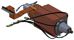
Figure 4 Spatium amplifier with clamp to conduct heat from the MMIC PAs.
An actual Spatium amplifier was designed that combined 16 radial blades with the Qorvo GaN MMIC PA on each blade. Figure 3 shows the measured output power versus clamp surface temperature; the baseplate temperature below the MMIC is approximately 12°C hotter than the clamp temperature, so the maximum baseplate temperature is 85°C. This unit achieves greater than 100 W from 2 to 7.5 GHz and an average efficiency of 25 percent.
THERMAL DESIGN
Thermal management is one of the design challenges when using a solid-state amplifier in an ECM transmitter. In a typical application, the outer surface of the clamp around the Spatium SSPA is conduction cooled on one or more sides (see Figure 4). For some systems, a liquid coolant may be available, for others a heat sink with fans. The clamp is designed to make contact with all of the blades in the Spatium and provide a conduction path to a cold plate or heat sink. Spatium blades and clamps can be made of different metals, including aluminum and copper. Size, weight and power trade-offs determine the appropriate material set for a given application.
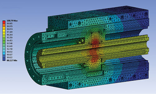
Figure 5 Thermal simulation of the Spatium SSPA, showing cross section of the construction.
The thermal resistance from the back of the MMICs to the mounting plates can be calculated and used to derive the backside MMIC temperature. From the thermal resistance of the MMIC and package, the junction temperature of the MMIC can be calculated and, from that, the reliability of the SSPA can be estimated. Figure 5 is a thermal simulation of the SSPA shown in Figure 4, with the MMICs operating at saturated output power and the worst-case efficiency within the frequency band (i.e., 25 W dissipated per MMIC). The thermal model shows an approximate 12°C rise from the coolest spot of the outside surface of the clamp to the backside of the packaged MMIC and an additional 164°C temperature rise from the back of the package to the junction of the output transistor, assuming 6.56°C/W thermal resistance. The junction temperature of the MMIC is estimated to be 247°C with the surface of the clamp held to 71°C. At 247°C junction temperature, the MTBF of the MMIC is some 1.2 million hours.
The MTBF of the overall Spatium module will be the MTBF of the individual MMICs divided by the number of MMICs: 75,000 hours. The calculation deems a single MMIC failure to be a failure of the entire amplifier assembly—a worst-case assumption since the Spatium amplifier will gracefully degrade with the failure of any individual MMIC (i.e., approximately 0.7 dB reduction in output power per MMIC failure).
For a TWT, MIL-HDBK-217F Notice 2 provides the following formula to calculate the MTBF in a ground fixed environment:

where P is the rated power in watts, from 1 mW to 40 kW, and F is the operating frequency in GHz, from 100 MHz to 18 GHz. Utilizing this formula, a TWT with an output power of 150 W at a frequency of 7.5 GHz has an MTBF of 29,609 hours. This is 2.5x lower than that of the comparable solid-state Spatium power amplifier module under similar environmental conditions.
SUMMARY
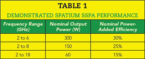
For the first time, GaN MMICs and broadband spatial combining techniques such as Spatium allow ECM system designers to use reliable, solid-state amplifiers instead of TWTAs. The ability to deliver hundreds of watts over broad bandwidths, while staying within the prime power available from the platform and dissipating the heat to ensure reliable operation, opens up new system opportunities for a solid-state ECM transmitter. Table 1 shows the frequency, power and efficiency achieved with three recent Spatium amplifiers. The size and weight of these SSPAs are less than the boxes previously occupied by their respective TWTAs.