A Transmit Frequency Converter for LMDS Set Top Box Applications
Vari-L Company Inc.
Denver, CO
A frequency converter module set suitable for set top boxes used in local multipoint distribution system (LMDS) applications has been developed. The module set has been designed in accordance with the standards established by the European Telecommunications Standards Institute (ETSI). Figure 1 shows a block diagram of the four-module set.
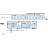 The upconverter module set comprises the part number SCM80/1440 80 to 1440 MHz upconverter module, part number SCM1440/550 1440 to 550 MHz downconverter module, part number SSM1520 1520 MHz phase-locked loop (PLL) module and part number SSM1990 1840 to 2140 MHz PLL module. The four modules are designed to be mounted on a PCB using standard surface-mount pick-and-place assembly techniques.
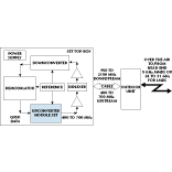
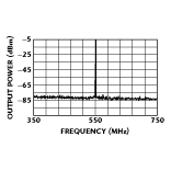 The set is intended to be used as part of an LMDS set top box composed of an upconverter and downconverter, a demodulator and reference oscillator, two RF amplifiers, a diplexer and a power supply. The box provides a 400 to 700 MHz upstream and 950 to 2150 MHz downstream that are fed via a coaxial cable to an outdoor unit that performs the air interface to and from the head end at 5 GHz for multichannel multipoint or 24 to 31 GHz for LMDS applications. The module set provides the 400 to 700 MHz upstream output frequency that is compatible with ETSI Standard EN301 199 paragraph 5.1.2 and features dual-conversion architecture that provides excellent spurious performance of less than -70 dBc, as shown in Figure 2 . A block diagram of a typical LMDS set top box is shown in Figure 3 .
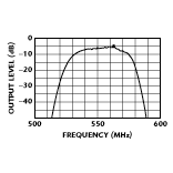
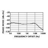
 The IF input supports a 30 MHz bandwidth signal at center frequencies of 55 to 85 MHz, allowing the user a wide selection of modulator center frequencies to drive the upconverter. Figure 4 shows the upconverter’s output bandwidth, which provides the user with wideband data transmit capability. The upconverter provides 35 dB of gain control range to account for the ETSI-required power range of 28 dB and cable losses in the system. (The indoor unit must set the range since no control signals go to the outdoor unit.) The two PLL modules allow the user to set the output frequency with a channel spacing of 25 kHz. Phase noise performance is -106 dBc/Hz at 50 kHz. Figure 5 shows the upconverter’s typical phase noise.
 Specifications for the module set include a fixed-frequency synthesizer (LO1) tuning range of 1480 to 1560 MHz chosen by the user based on an input frequency of 55 to 90 MHz and a 1440 MHz IF. The LO1 step size is 1 MHz. The frequency-agile synthesizer (LO2) has a tuning range of 400 to 700 MHz with a 25 kHz step size (50 kHz is also supported). The two LO signals must be programmed with the four-wire serial interface to achieve proper operation of the upconverter assembly. Information on calculating the required LO frequencies and commanding the LOs is supplied with the module set.
 The RF path features a 10 dB/V (typ) automatic gain control (AGC) range and an AGC response of 300 Hz for < 3 dB attenuation and 50 kHz for > 50 dB attenuation. The AGC input requires 0 to 5 V into 10 kW (min). The 1 dB bandwidth is > 10 MHz, while the 60 dB bandwidth is 30 MHz < F < 160 MHz. Noise figure is < 22 dB at -5 dBm output and < 35 dB at -30 dBm output. Group delay ripple is < 20 ns p-p. The RF output frequency range is 400 to 700 MHz at a -35 to -5 dBm level. Output power variation vs. frequency is < 3 dB over 400 to 700 MHz at any one AGC setting. Worst-case spurious signals are -65 dBc in the 700 to 1900 MHz range and harmonics are < -20 dBc (max). The third-order intermodulation point is < -45 dBc with two -30 dBm tones applied to the input.
The IF input frequency range is 55 to 85 MHz with a typical bandwidth of 10 MHz. IF input power is -25 ±3 dBm with an input return loss of ³ 9.5 dB. The reference input is 4 to 40 MHz into >10 kW at a 0.3 to 2.2 V p-p input level. DC power is 8 V at 100 mA or less and 5 V at 120 mA or less. The module set is designed to operate over a -30° to +80°C temperature range at 0 to 95 percent noncondensing humidity. An evaluation PCB is available from the manufacturer for testing the set.
High temperature solder is used internally on the modules to allow installation with standard surface-mount reflow techniques. The modules are supplied on tape-and-reel to facilitate automatic assembly. Prices: $130 (1000); $60 (100,000). Complete specifications may be obtained from the manufacturer by phone request or via e-mail at sales@vari-l.com.
Vari-L Company Inc.
Denver, CO
(303) 371-1560
