Prematching Tuners for Very High SWR and Power Load Pull Measurements
Focus Microwaves
Ville St-Laurent, Quebec, Canada
Load pull testing of high power transistors in the PCS and cellular frequency range (0.85 to 3 GHz) requires accurate tuning capability around 1 W output impedance or less. Meanwhile, RF power handling capability of the tuners beyond 50 W at very high SWR is a must. The traditional approach to respond to these requirements is to use low characteristic impedance (for example, 10 or 20 W) l/4-long microstrip transformers on the test fixture, which allow the test set to effectively tune around the 1 W or less impedance range. However, this type of solution presents three major inconveniences: limited bandwidth of less than 10 percent, a fixed tuning direction (typically, but not always, 180°) and a fixed transforming ratio. These drawbacks mean that for every new transistor and frequency, new transformers must be designed, manufactured, characterized and assembled. Prematching probes used for low impedance testing on wafer have the same disadvantages as long as they are narrowband. Wideband transforming probes have the disadvantage of targeting only the 180° area of the Smith chart (Z » 0 W).
In view of these limitations, new tuning instruments with high SWR capability and bandwidth and an adjustable target tuning range are required. The PMT-xxyy series prematching tuners utilize the tuning capability of two independent tuning sections and have proven to be a major breakthrough in very high SWR testing by providing simultaneously high power handling, bandwidth, calibration accuracy and versatility for testing various types of power transistors. SWRs beyond 100 (Z » 0.4 W) combined with two to three octave bandwidths, a 360° target tuning area and 50 to 150 W RF power handling are standard performance, depending only on connector type and frequency range.
Principle of Operation
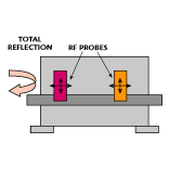 Prematching is the process of generating a total reflection in two steps, as shown in Figure 1 . The first step brings the device impedance from a very low level to a medium level and the second step brings it to 50 W. This prematching can be done on chip using lumped elements such as capacitors and bonding inductors or on microstrip using low characteristic impedance l/4 transformers. Wideband prematching is possible using either more than one step transformer or tapered transmission line sections where the characteristic impedance change occurs gradually. In this case, bandwidth is gained at the cost of size (tapers are long).
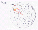 Prematching at a single frequency consists of adding two reflection factor vectors at the right phase to generate a larger one, as shown in Figure 2 . Prematching tuners use this patent-pending technique. The first probe generates a reflection vector that is added to the reflection of the second probe. The combination generates a total reflection factor that reaches 1.0 at the reference plane of the first probe. Losses in the transmission line between the connector of the tuner and the first probe limit this total reflection to values between 0.98 and 0.95 or SWRs between 100 and 40.
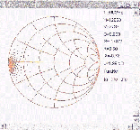
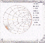
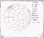
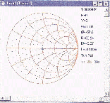 Figures 3, 4 and 5 show how PMT tuners focus on a particular area of the Smith chart by adjusting the characteristic impedance of the prematching section. Figures 6 and 7 show how PMT tuners select the phase of the target tuning area even at maximum SWR. The advantages of this technique are that Gmax reaches almost 1, Fmax can be shifted through probe 1 and each probe does not need to generate
 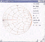 excessive SWR. In addition, any frequency can be tuned and when the tuner is initialized the system has 50 W) impedance (avoiding parasitic oscillations). Two further benefits are provided due to the two-probe configuration: Power handling capability at very high SWRs increases because there is less risk for corona discharges between the RF probe and the central conductor, and calibration accuracy improves due to the lower Gmax of each probe.
 However, there are also potential inconveniences caused by this technique. Because, in reality, the system includes two independent tuners, the combined calibration time may be too long for practical considerations. If each tuner is calibrated at 400 impedance positions per frequency, then the combination should be calibrated at 400 x 400 = 160,000 points per frequency. At an average of 10
 minutes per tuner per frequency, this means three days per frequency -- an unacceptable calibration time. Consequently, a new patent-pending tuner calibration technique has been developed that allows the complete tuner to be calibrated in a maximum of 20 minutes per frequency for all 160,000 impedances. In addition, the associated software allows interpolation between calibration points, which drives the impedance multiplexing capability of the new tuners into the hundreds of millions.
 Conclusion
The PMT tuners using the new calibration technique and interpolation routines represent a continuous tuning device with fine tuning resolution equivalent to manual tuners. Additional information is available on the company’s Web site at www.focus-microwaves.com.
Focus Microwaves
Ville St-Laurent, Quebec, Canada
(514) 335-6227.
