

Waveguide twists are necessary for waveguide systems and subsystems that require a change in the polarity of a signal to phase match with a load. To support these needs, Fairview Microwave has released a family of waveguide twist assemblies with seven different sizes that operate in distinct bands from 18 to 110 GHz. These waveguide twists cover applications in K-, Ka-, V- and W-Band and are optimally designed for instrumentation, precision measurements, prototyping, characterization and production systems.
These precision assemblies are available in standard WR-10, WR-12, WR-15, WR-19, WR-22, WR-28 and WR-42 sizes. With compact lengths ranging from 1" to 2.5", these components fit conveniently into any waveguide setup. To support the wide variety of waveguide installations, each waveguide size features 90° and 45° offsets in either the left-hand or right-hand twist plane. Fairview’s twist waveguide interconnect family uses brass-body construction with gold plating. Gold plating reduces resistive losses along the interior walls of the waveguide, improving the conductivity and surface condition of the waveguide walls. As the depth at which electrical current travels in a conductor is frequency dependent, a phenomenon known as the skin effect, higher frequency conductors benefit from improved conductivity at the surface, which leads to lower attenuation and less reflection back to the source.
Figure 1 Using a waveguide twist to test E- and H-plane radiation patterns. Source: Microwave Engineering: Concepts and Fundamentals, Ahmad Shahida Khan.
From K-Band radar antenna feeds to Ka-Band communication satellites to V- and W-Band test systems, the waveguide twists can be integrated in a wide range of waveguide systems. For example, a test bench setup that requires convenient switching between H-plane and E-plane measurements can alternate between a rectangular waveguide twist and a rectangular waveguide. Measuring E- and H-plane radiation patterns with horn antennas just requires the addition or removal of a waveguide twist (see Figure 1). Another illustration of a waveguide twist application is using a twist to change the polarization of the signal in a waveguide antenna feed for military radar (see Figure 2). Waveguide twists are used in front-feed installations to avoid obstructing the aperture of the larger parabolic antenna.
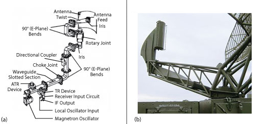
Figure 2 A waveguide twist (a) used in the antenna feed of a military radar (b). Source: Wikipedia, en.wikipedia.org/wiki/Waveguide#/media/File:Radar_waveguide.jpg, CC BY-SA 4.0.
Figure 3 The WR-22 90° twist (SMW22TW1001) has a maximum insertion loss of 0.5 dB and VSWR of 1.02:1 between 33 and 55 GHz. The measured |S11| is the reflection from the load used to test the twist.
To reliably serve the diverse range of applications, Fairview Microwave fabricates all waveguide in accordance with MIL-DTL-85, which is the military specification for the performance requirements for rigid waveguides with rectangular inside configurations. These standards govern the mechanical and electrical performance of the waveguide. MIL-DTL-85 specifies that any waveguide twist must have at most 1 degree of rotation per foot of length along the axis, as well as defining the maximum allowable surface roughness and scratches, to ensure a conformal waveguide and allow for a continuous impedance along the waveguide. The angle of the twist is measured on a flat surface as a reference plane, using an engraved protractor adjusted to a particular angle line. To verify that the waveguide twist meets pressurization standards, it is subjected to forced internal air pressure while submerged in water heated to 68°F for five minutes. A failure occurs in the pressure test if air bubbles are released from the edge seams. VSWR and return loss are also specified to ensure minimum reflection and peak electrical performance.
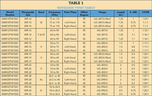
The insertion loss of Fairview Microwave’s 21 different waveguide twists range from 0.2 to 0.75 dB in K- and Ka-Band to 0.5 to 1.1 dB in V- and W-Band. The VSWR can extend between 1.07:1 to 1.25:1 in K- and Ka-Band and from 1.02:1 to 1.43:1 in V- and W-Band. Figure 3 shows the low insertion loss and high return loss of the SMW22TW1001 90° waveguide twist.
Table 1 summarizes the electrical performance and mechanical construction of the waveguide twist family. Seven waveguide sizes are in stock, each with 90°, 45° left-hand and 45° right-hand twists available. Waveguide sizes WR-22, WR-28 and WR-42 are 2" or longer, while WR-10, WR-12, WR-15 and WR-19 are 1.25" to 1.5" in length.
Fairview Microwave’s portfolio of waveguide twists are a part of a large suite of precision waveguide. With one of the largest portfolios, Fairview Microwave can serve many “waveguide plumbing” needs across commercial, military and precision test applications.
Fairview Microwave Inc.
Allen, Texas
www.fairviewmicrowave.com