
While it’s true that the primary function of an RF coaxial cable assembly is to make an electrical connection between two parts of a system, equipment, sub-assembly or test set up, there is so much more to its specification than just the electrical parameters that define the basic interconnection performance. The environments in which RF coaxial cable assemblies are used are incredibly varied, from static benign, as might be the case in ground-based, room temperature equipment racks, right through to space platforms where the ultimate in reliability is demanded.
It will come as no surprise to the RF test engineer, however, that one of the harshest operating conditions is found in the laboratory, on the test bench. The cable assemblies used to interconnect items of test equipment and connect to the device under test (DUT) may not only be subject to all the environments that the DUT is expected to survive but also to that indefinable form of stress, human handling.
Laboratory test cable assemblies have to withstand extremes of temperature, vibration, shock and handling while delivering a level of electrical performance, which ensures that the measurements of the DUT are minimally compromised. With AtlanTecRF’s ACV series of RF test cables the cable construction is built up in multiple layers in order to reduce the compromises and provide the user with the optimum interconnect during the testing routine.
In the ACV-CA40 and ACV-CA50 series, for use at 40 and 50 GHz respectively, the basic electrical performance is provided by the silver-plated solid copper centre conductor, low density PTFE dielectric and silver-plated copper ribbon outer conductor. Together with the PTFE stabilizing layer and the silver-plated copper braid, these five inner layers define and guarantee the impedance, insertion loss, phase and amplitude stability which are so critical when the test set up is subject to constant movement and temperature extremes.
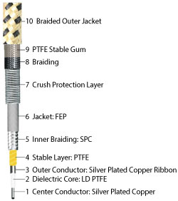
Figure 1 Construction of the ACV series cable.
On top of this inner core, the next five layers both reinforce the mechanical and therefore electrical stability and add the vital ingredient of protection against constant handling. The jacket over the braid is FEP and this is further protected but a proprietary crush resistant layer held in place by a further braid and PTFE gum. The final, 10th and outer jacket is of proprietary braided fabric to ensure a high level of resistance to the abrasion potential derived from repeated handling. A complete cross section of the ACV series cable is shown in Figure 1.
The test laboratory contains both expected and accidental stresses on test equipment and this is particularly true of the cable assemblies with high probability of being snagged or caught beneath heavy objects. The two features of crush protection and abrasion resistance, although difficult to quantify, are key in the value provided to the test engineer.
Moving on to the more easily defined electrical and mechanical parameters; the ACV series is available in both standard and custom lengths. The standard, stocked lengths are 0.5, 1, 1.5 and 2 m, being the most popular for bench testing with vector network analyzers (VNA), spectrum analyzers and other items of high performance RF and microwave test gear. Lengths can be customized however for automated test set ups where excess cable length is kept to a minimum.
The two connector series, 2.92 mm for use to 40 GHz and 2.4 mm for use to 50 GHz are among the most common found in today’s RF test world and are both precision made in stainless steel. The multi-layer strain relief at the back end of each connector does much to guard against work hardening and fatigue of vital cable elements at this vulnerable point.
Figure 2 Loss and VSWR of the ACV series cable.
The 10 layer construction previously described endows stability under flexure of ±0.03 dB in amplitude and ±5° in phase, both of which are necessary to ensure accuracy and repeatability of RF test results. Basic RF performance is excellent with less than 5 dB insertion loss per meter and an assembly VSWR of typically 1.2:1 at the top end frequencies (see Figure 2).
Over the ‐55° to +165°C operating temperature range too, these cables show little variation in phase with 1000 ppm being typical. Many laboratory tests need to be carried out in temperature cycling chambers to the full range of the DUT and the test cable’s ability to track and maintain performance during such tests is essential.
Once more, the well thought out multi-layer design scores with over 90 dB RF shielding, which is a serious consideration in the test environment. Additional figures in the electrical data listings include a capacitance of 138 pF, withstand voltage of 1000 V, power handling up to 115 W at 12 GHz and insertion loss variation during flexing of no more than ±0.05 dB.
Despite the complex 10-layer construction, great care has been taken to minimize the weight of the cable as this, in itself, can add to the stresses applied. At just 35 g/m therefore, the assemblies are about as lightweight as any that can be found for such a demanding task or many other applications.
With all of the performance and durability so far described, the ACV series of 40 and 50 GHz flexible test cable assemblies have yet another killer asset, a bend radius down to 40 mm, which should grab the interest of RF and microwave test engineers everywhere.
AtlanTecRF
Braintree, U.K.
www.atlantecrf.com