
EMPIRE XPU is a 3D EM design suite for antennas, microwave circuits and components, EM chip design, medical applications and more. Since its original introduction to the market, it has been recognized as a key tool for the EM design of complex structures. The new release 7.5 follows that tradition with enhancements now able to handle structures up to hundreds of wavelengths in size.
Aiming to be faster on CPUs than others on GPUs the EMPIRE XPU offers fast and accurate 3D EM and thermal simulations of complex RF build-ups and modules using off-the-shelf PC equipment. With this tool the time-to-market can be reduced to a bare minimum. Because of the high accuracy of the simulation results, prototype cycles are considerably shortened and hence development costs are reduced.
EMPIRE uses XPU technology, which is an IMST proprietary software acceleration technique specifically developed for running FDTD simulation on modern CPUs. A multiple time stepping algorithm enables the calculation of multiple FDTD time steps in the cache memory of the CPU. Just In Time (JIT) compilation ensures the best fitting code for both the hardware used and simulation model.
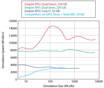
Figure 1 FDTD simulation speed vs. simulation size for different processors (CPU and GPU).
This combination increases the simulation speed drastically as it is no longer limited by the main memory interface. The whole RAM memory of the PC is now ‘high-speed’ accessible for the EM simulation. With this highly optimized kernel 3D EM simulations have seen processing rates of over 14 GCells/s on Intel Xeon workstations. Figure 1 compares the simulation performance of the EMPIRE XPU on different workstations vs. GPU computing.
INTUITIVE MODELING
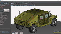
One main feature of the EMPIRE XPU 7.5 release is a new 3D design modus with an enhanced modeling kernel and direct import and export options for all major 3D CAD formats. The 3D design mode allows intuitive modeling and supports unlimited local coordinate systems. It complements the 2D design mode with superior editing functionalities for planar multilayer designs. As data exchange between different software tools becomes more and more important, EMPIRE supports the import of EM simulation vendor projects.
To be as flexible as possible when it comes to the hardware for EM simulations, EMPIRE XPU 7.5 supports cloud computing. The Amazon Elastic Compute Cloud (EC2) can be easily directly accessed via an encrypted connection from the EMPIRE simulation control. Floating licenses can be used to perform simulations on every PC. The Amazon EC2 provides a large selection of instance types worldwide, fitting all simulation needs from small single core PCs up to large 64 core workstations with 2TB main memory.
To help customers support U.S. government compliance requirements, including the International Traffic in Arms Regulations (ITAR) and Federal Risk and Authorization Management Program (FedRAMP), Amazon offers an isolated AWS region designed to host sensitive data and regulated workloads in the cloud (AWS GovCloud US).
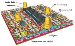
Figure 2 RF circuit and interface side of Ka-Band 5G front-end module.
EMPIRE XPU 7.5 is well suited to designing highly integrated RF front ends at microwave frequencies. Front ends are a key component for K/Ka-Band satellite communications on-the-move, multimedia entertainment systems and 5G base stations as well as 60 GHz broadband home access equipment and backbone networks. Designing such complex modules were a real challenge in the past but not anymore with EMPIRE XPU.
As an example, the DBF Ka-Band/5G front end module (digital beamforming), which is shown in Figure 2 is designed using EMPIRE XPU. Each front end consists of a low temperature co-fired ceramic (LTCC) module with an 8 × 8 patch antenna array on the underside (see Figure 3), integrated active RF electronics and cooling system.
MODULAR APPROACH
A modular design approach is used to combine several modules for a larger array in order to fulfill the requirements dictated by the specific application. This modular approach requires a design where all RF and DC electronics including cooling must fit behind the antenna area. The antenna area for each patch element is limited by the antenna element spacing, which is half a wavelength. A larger distance between the antenna elements would degrade the antenna performance with respect to the sidelobe level, grating lobe level and scan range.
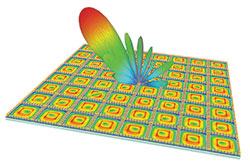
Figure 3 Antenna side of Ka-Band 5G front-end module, showing electric near field and 3D far field.
The antenna element area for this Ka-Band antenna design is 5 mm × 5 mm. This is a small space especially for a DBF antenna as each patch element needs its own chipset consisting of mixer, filter and PA with IF and DC connections to allow for amplitude and phase control at baseband level.
The design flow for this LTCC module started with the design of the patch antenna, the 90° hybrid circuit and the calibration network. Next, the RF chipsets were integrated together with the connectors on the top surface of the LTCC. The design of the LO network and the IF network was done afterwards. Finally, the antenna and the RF parts were integrated into one LTCC module.
It is important to simulate the complete module with a full wave 3D EM simulation tool to include all parasitic couplings between the different elements. Retuning of the LO network and some antenna paths were necessary to compensate for these parasitics. In addition to the RF characterization, the complete module simulation allows for layout errors such as shorts or open circuits to be checked. This simulation technique ensures a short turnover from design to manufacturing, even for such a complex design with more than 40,000 objects. The simulation of the complete LTCC module needs about 16 GB memory and a simulation time below two hours on a modern Intel Xeon workstation.
IMST GmbH
Kamp-Lintfort, Germany
www.empire.de