
Modern radar systems are exceptionally complex, encompassing intricate constructions with advanced technologies from multiple engineering fields. Accurately detecting moving targets in these multifaceted environments is difficult, given the detrimental effects of interference on precision measurements. The adoption of a simulation technique provides a design-oriented value proposition of shortening the development period, saving time and money by avoiding unnecessary field tests. This measurement solution promises lower product risk, reduced cost, higher system performance, customization and ease of use. The following discussion examines an alternative simulation method that allows for better cross-domain modeling in a single framework, to capture the complete effects of modern radar system performance.
INCREASING ACCURACY, DECREASING COST
The interference involved in mobile radar measurements poses a large challenge for radar designers and operators. Any form of interference in the radar system floods the receiver with irrelevant and distracting noise or false information. This overload of unwanted data makes it impossible to analyze and measure the desired data. The system is essentially overrun with irrelevant information, and no essential data may be collected. In order to properly address these issues in mobile radar measurement, it is optimal to create a simulation of the scenario.
The use of a simulation allows for elimination of interference, guaranteeing accurate measurements. The scenario framework simulation (SFS) technique can be easily implemented, lessening the difficulties involved in testing. The use of the SFS technique presents a solution to the problems faced during the performance of mobile radar measurements. Expenditures are decreased, while accuracy and efficiency are boosted. Any scenario may be modeled, measured and accurately understood, enabling superior performance in the physical application of the scenario. The advantages of the SFS are:
- Models any system, including monostatic ground-based systems, more complex multistatic systems and phased arrays
- Supports motion of radar transmission and receiving platforms and targets
- Eliminates field testing costs, increasing efficiency and reducing test times.
Designing advanced radar systems is a challenge when one considers the complexity of the operating environment and the fact that these systems are becoming less reliant on traditional RF design and pushing more functionality in baseband signal processing and digital signal processing (DSP). The ability to model the complexity of the operating environment while accounting for the interaction between baseband, DSP, RF and antenna systems can be a real challenge with existing system-level engineering methodologies.
Further, it is vital that new systems capable of providing operational differentiation and advantages be deployed quickly. Not only does this provide tactical advantages, it also delivers economic advantages to the companies who can deploy systems most quickly and with the highest performance and capability. Radar designers demand a platform for testing radar receiver processing algorithms with the capability to handle complex operational environments. Simulation fulfills these demands and moves testing into the lab. The extensive expenses involved in field testing places a burden on the tester. The use of simulation promises not only the most accurate results, but also the least expensive and most expedient path to accurate data.
SCENARIO FRAMEWORK SIMULATION
To better understand the importance of implementing this simulation technique, an explanation of how it functions is beneficial. Given the number of different radars, and the inconsistencies between them, a generalized simulation tool is essential to accurately model all scenarios. A standardized simulation uses the basic assumptions involved when testing radars: no matter what type of radar, the signals are always transmitted from some radar system and received by themselves or by other radar systems. When using the SFS, this standardized simulation is implemented.
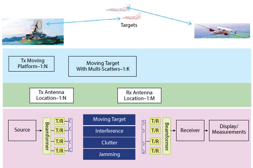
Figure 1 Scenario framework simulation using SystemVue software. Simulation replicates any radar scenario, eliminating the need for costly field testing.
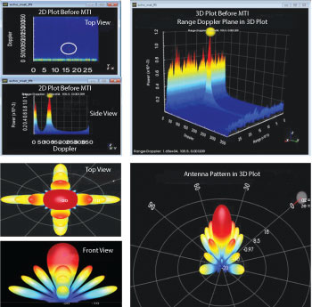
Figure 2 SystemVue simulation supports advanced measurements, including detection and false alarm probabilities. The program can account for interference and remove it from the data and results.
While setting up the simulation framework in the testing device, there are three layers to consider: the trajectory layer, the antenna layer and the signal layer (see Figure 1). The trajectory layer locates all receivers and transmitters in 3D position, velocity and acceleration spaces. A radar platform model and radar target trajectory model are used to compute the trajectories. The antenna layer tracks the rotational attitude (i.e., pitch, yaw and roll) and beam forming directions. The azimuth angle and elevation angle of the targets in the antenna frame are computed to calculate the final antenna gain. The signal layer measures the traditional baseband signal processing paths, using MATLAB, HDL and RF models. The signals are delayed, attenuated and amplified by the antenna and transmit/receive (Tx/Rx) chains.
The signals received by radar systems are the signals from transmitters and the echoes from targets or the different scatters of targets. The distances between transmitters and targets, and between targets and the receiver, determine the delay values of each sample of echoes, which finally determine the magnitude attenuation and Doppler frequency. In addition to the above parameters, the position between the transmitter and the target and the direction of the antenna main lobe relative to the antenna carrier determine the transmitter antenna gain. The same is true for the receiver antenna gain. Given this basic framework, one can model any number of radar systems.
Once the various layers of the simulation are set up, one can begin to make many different types of advanced radar measurements, ranging from basic spectrum or signal-to-noise ratio (SNR) to detection and false alarm probability. Figure 2 illustrates several plots that can be generated to provide a detailed visual of the simulation.
Now that the basic system set up and functionality of this simulated approach are clear, a specific example is presented to demonstrate the capability this scenario has of solving difficulties associated with mobile radar measurements.
OVERCOMING INTERFERENCE
The advantages of implementing an SFS technique are underscored when applying its capabilities to a specific model, such as an airborne radar in lookdown mode with surface clutter, where the operator wishes to simulate a moving platform that is also tracking a moving target. In this scenario, there are several considerations to be addressed to fully and accurately simulate the setting: surface clutter, target RCS and any jamming/deception techniques used by an opposing threat. When performing measurements, there is much interference. One of the main issues faced in moving radar measurements is clutter. Surface clutter essentially refers to any area-based clutter that can exist on both land and sea and typically becomes an issue in airborne radars in the lookdown mode. To adequately account for clutter and all other forms of interference, several measurements must be performed precisely to obtain accurate results:
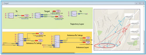
Figure 3 Trajectory and antenna layer setup.
- Waveform and spectrum calculation of detection probability
- Creation of 3D plots of the range-Doppler plane
- Estimation of range and Doppler effects.
The first step in setting up the simulation is to construct the three layers previously discussed. For the platform setup, assume the airplane is flying with a certain velocity VT and the initial location in LLA is longitude R, latitude R and altitude R. Using the radar platform model, Tx, the Tx and Rx platforms in the trajectory layer are specified as seen in Figure 3, with the same for the target model. Target location and speed can be set using the radar target model. If the user wants volume target, this model also allows specifying multi-scatters in one target.
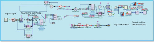
Figure 4 Signal layer setup.
Once the signal layer has been set up, as shown in Figure 4, the physical layer setup is considered. A linear FM (LFM) signal is used by default. Custom waveforms such as nonlinear FM (NLFM) or coded signals can also be used. Under the “RF Transmitter” parameter, there are several options with which the data can be formed, including analog/digital and cross-domain simulation. Phased array models are available. Detection environments such as target RCS, clutter, jamming/deception have been considered. A radar signal processing algorithm, such as MTI or MTD, is put in the radar receiver. Once the layers have been set up, many measurements can be used to characterize the different elements of the scenario (see Figure 5).
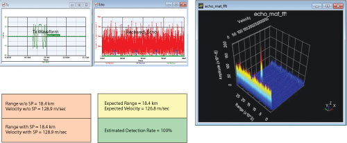
Figure 5 With the platform setup, the user can adjust and measure all forms of interference.
To summarize, the three layers were set up, the physical layer was formed, the detection environment (clutter) was considered, and now appropriate measurements may be performed. All forms of interference may be accounted for and accurately modeled in this system framework. This simplistic approach to airborne radar measurements demonstrates not only its power but also the ease of use. This example may be modeled on any number of different radar scenarios; the universal quality of the SFS enables testing of all kinds of radar signals and situations. Once the basic framework has been achieved, any environmental interference may be easily accounted for within the calculations of the software, guaranteeing accurate results. Radar scenario simulations can be challenging to design and test, especially when they are airborne. The new simulation approach successfully addresses these challenges.
To save development time and reduce cost, simulation of different radar scenarios is paramount. These scenarios can include radar signal generation and processing, as well as environmental effects and simulated platform and target hardware specific parameters. The capability to simulate the full deployment environment enables exceptional development speed and provides rapid prototyping capabilities for any radar system development. By moving testing into the lab and away from the field, time and money are saved, while measurement accuracy is improved.