
In the evolution of front-end mobile applications, the number of antennas is growing to reflect the demand for more frequency bands and better signal quality. RF switches play a vital role in the circuitry in these smart mobile devices, as they route signals through an array of antennas. With the use of GaN in communications systems, RF components are offering higher power density in smaller packages, increasing system range and sensitivity. The switches in these systems need to keep up with these capabilities, particularly power handling. RF switches are integral to Wi-Fi access points and base stations, switching between transmit and receive signals. In test and measurement, switches automate routing among test instruments and the device under test, simplifying setups that conventionally require manually connecting and disconnecting various ports to gather the needed data. Military systems and satellite communication also require robust, high performance and high power RF switches.
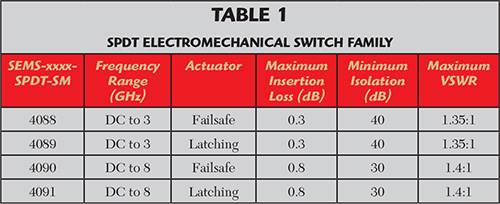
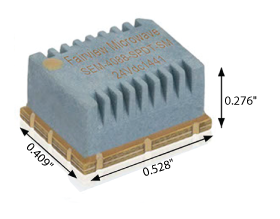
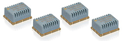
Figure 1 All the switches in the SPDT family are in small footprint, rugged SMT packages.
To meet these wide market needs, Fairview Microwave offers a family of four high reliability, high power, surface-mount (SMT), single pole double throw (SPDT) electromechanical switches (see Table 1). Two models cover DC to 3 GHz and two extend the upper end to 8 GHz. All are 50 Ω. Failsafe and latching actuators are available for each frequency range. A latching actuator will maintain the chosen RF path with or without the operating voltage, while a failsafe actuator will switch back to the de-energized state when no voltage is applied. All the switches operate with a control voltage of 24 V; the failsafe models require an actuating current of 25 mA and the latching models require 32 mA.
Fairview Microwave’s electromechanical switches are compact (see Figure 1), requiring minimum real estate on a printed circuit board (PCB), and lightweight, weighing only 1.81 g. Despite the small size, these switches have rugged housings to prevent damage or degraded performance during vibration and mechanical shock. Designed for high reliability, the switches operate from -40° to +85°C, deliver lifetimes of over 2 million switching cycles, are RoHS compliant and have a gold-plated mounting surface to enhance the contacts and resist oxidation.
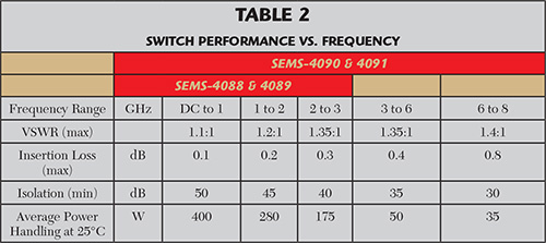
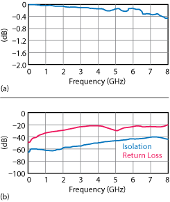
Figure 2 Typical insertion loss (a) isolation and return loss (b) of the SEMS-4090-SPDT-SM switch.
Table 2 summarizes the performance of the switch family over frequency. The maximum input power handling is 400 W CW at +25°C up to 1 GHz. Above 1 GHz, power handling declines to 175 W at 3 GHz and for higher frequency switches, 35 W at 8 GHz. Maximum insertion loss is 0.1 dB at 1 GHz and rises to 0.3 dB at 3 GHz and 0.8 dB at 8 GHz. Isolation is 50 dB minimum at 1 GHz, dropping to 40 dB at 3 GHz and 30 dB at 8 GHz. Maximum VSWR ranges from 1.1:1 at 1 GHz to 1.35:1 at 3 GHz and 1.4:1 at 8 GHz. Figure 2 shows the performance vs. frequency of the SEMS-4090 model.
To ease designing the switches into a system, Fairview Microwave offers PCB layout software that can be downloaded from the product pages on Fairview’s website.
Pricing begins at $239 for the 3 GHz switches and $263 for the 8 GHz models. All products in the family are available for same day shipping, and all are classified EAR99 for export.
This family of SPDT electromechanical switches serves a wide variety of markets and applications that demand high reliability, low loss and high power handling performance. The small size and rugged package enable use in systems with limited PCB footprint.
Fairview Microwave
Allen, Texas
www.fairviewmicrowave.com