
A compact communication platform employing four antennas is designed for LTE MIMO applications. It includes one pair of small MIMO antennas with a zeroth-order resonator (ZOR) in-phase electric field distribution and another pair of MIMO chip antennas. The radiators are 9.0 mm × 5.5 mm and 12 mm × 3.0 mm, respectively, and are placed on the top and bottom edges of a realistic handheld device. The design operates in the 2.4 GHz LTE band. Antenna gain is greater than 1.3 dBi, and isolation is greater than 10 dB for all antennas.
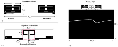
Figure 1 The two MIMO antennas placed on the top edge of the hand held device; top-view (a) bottom view (b) the two antennas installed on the top edge (c).
Multiple input multiple output (MIMO) antennas offer higher quality mobile communication by providing RF isolation in diverse signal environments. Designers have been challenged to reduce antenna size while increasing isolation between the multiple antennas.1-14 Mak et al.,1 introduced a set of antennas with a structure that traps the near field from one antenna to the other based upon a local current loop disconnecting a fictitious enlarged loop in order to increase isolation. The antennas have acceptable radiation patterns and isolation, but are large; the radiators and the trap occupy the top edge and two sides of a handset. Payandehjoo et al.,2 adopted an EBG geometry to increase diversity gain by preventing coupling between antennas. Its size, however, exceeds the industrial standard and its working frequency is not within the WiMAX band. Wang et al.,3 introduced two microstrip-fed antennas whose layered radiating parts stand perpendicular to the handset stratified ground with a folded and periodically meandered decoupling structure for improved isolation. Although this provides greater than 12 dB isolation, it has a microstrip-fed monopole-type decoupling geometry and three-dimensionally folded radiators that occupy a large area.
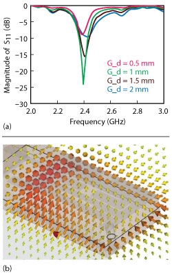
Figure 2 Parametric sweep and field at the ZOR; return loss of the CRLH MIMO antenna as a function of G_d (a) ZOR electric field (b).
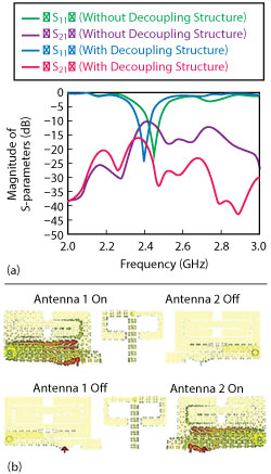
Figure 3 Predicted isolation (S21) before and after adding the planar mushroom; S-parameters (a) surface currents on the top two MIMO antennas.
Simple meandered quarter-wave radiators are separated with a split ground by Sharawi et al.,4 and a hybrid coupler by Bhatti et al.5 Although, in the latter case, the radiators are connected with an LC-based branch coupler for reduced coupling, three-dimensionally folded monopoles share a shorted loop for better decoupling in the design by Han and Choi.6 Taking a different approach, a very compact radiator using a double-layered CRLH loop is adopted for miniature symmetrically-shaped MIMO antennas by Yoo et al.14 The total size of the structure occupies two-thirds of the top edge of a handset device, gain is greater than 0 dBi and isolation is greater than 12 dB.
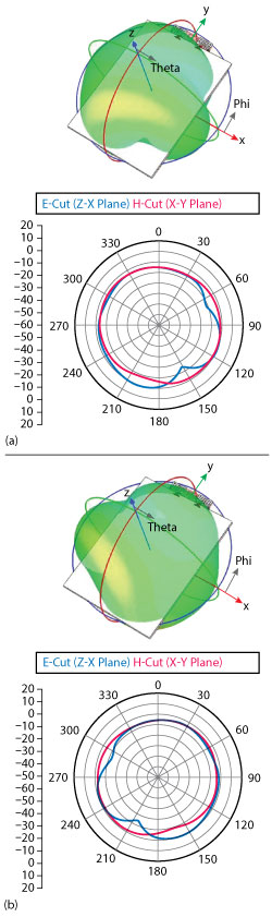
Figure 4 Simulated radiation patterns of the top two MIMO antennas; Antenna 1 (a) Antenna 2 (b).
In this work, four MIMO antennas are demonstrated, having a compact size suitable for use in a mobile handset. In contrast with the dual antenna approaches,1-13 two pairs of antennas form a densely populated antenna structure within a 54 mm × 80 mm area. One pair consists of two small radiators and a decoupling device between them, similar to that of Yoo et al.14 Each radiator is designed to resonate with the in-phase electric field distribution of the coupling rings in a 9 mm × 5.5 mm footprint, and radiate with the peak-gain over 1 dBi. These ZOR radiators are placed close to each other, but the decoupling structure provides isolation greater than 10 dB. The other pair employs modified monopoles, each smaller than 12 mm × 3 mm. The first pair of antennas sits on the top edge of the platform, and the second pair is placed on the bottom edge.
CRLH ZOR ANTENNA DESIGN
The specifications are f0 = 2.4 GHz, return loss |S11| ≥ 10 dB, antenna gain ≥ 1 dBi, efficiency ≥ 50 percent and isolation |Sij| ≥ 10 dB. The antenna elements are similar to split ring resonators (SRR) in the sense that their inner open-gap rings are surrounded by their outer rings. Different from an ordinary SRR, however, is that one corner of the outer ring is connected to an upper transmission line (UTL) coupled through the electric field while the other end is connected to a lower transmission line (LTL) attached to ground, resulting in composite right and left-handed (CRLH) properties.
The antenna elements’ SRRs and the UTL are located on the top surface of a 2 mm thick FR4 substrate whose bottom surface contains the feed points to the handset ground, the planar mushroom (decoupling structure) and the LTL as shown in Figure 1. Since a conventional SRR has a right-handed resonance, it seems unsuitable, at first sight, for effective size reduction. Therefore, each of the antennas uses the SRR as the series capacitance (CL) and part of the series inductance (LR) in implementing the CRLH zeroth-order resonance. Simultaneously, the electric field coupling and current flowing between the upper and lower transmission lines determine part of the shunt capacitance (CR) and the shunt inductance (LL), respectively. In addition, the LTL influences LR and CR. These factors are adjusted to make the SRR smaller. For this, a parametric study (see Figure 2) is conducted.
Because G_w and G_d affect impedance matching and CR, return loss (|S11|) is investigated when G_d is varied. G_d ranges from 0.5 to 2.0 mm and four samples are taken. With a 10 dB criterion, G_d values of 2 mm and above are acceptable as shown in Figure 2a. This implies that a certain collective shunt capacitance of CR is required, maintaining G_d. Figure 2b shows that the in-phase variation phenomenon with one-direction electric field vectors (all directed upward) is generated at the ZOR frequency. When the ZOR condition and resonance conditions are met, the following values are obtained for the geometrical parameters: A_h=5.5 mm, A_L = 27 mm, P_1 = 9 mm, G_d = 1 mm, A_p = 3.2 mm, D_w = 6.5 mm, D_h = 3 mm, M_L = 80 mm, and M_W = 60 mm with 2 mm-thick substrate of εr = 4.3 and loss tangent (tanδ) = 0.025.
To achieve isolation greater than 10 dB, the planar modified mushroom decoupling structure of Figure 1 is used. Typically, a mushroom is a 3D structure made up of a surface patch with a shorted via, and plays the role of bandstop filter that can be broadened in the form of arrays. For this application the mushroom is modified to fit into a planar structure. The arms are made longer and bent twice to make branch loops, increasing the shunt capacitance due to the narrowed gap between the ends of the arms and ground. The capacitance of the mushroom resonates with the higher inductance of the loop in the arm, when the magnetic field from one radiator passes the loop. This acts as a bandstop filter.
As shown in Figure 3a, with the planar mushroom as the decoupling structure, isolation is increased from 9 to 16 dB. The surface current densities are plotted in Figure 3b to visualize how the increased isolation is obtained. The decoupling structure draws surface current due to the near field from one excited antenna and plays the role of a trap; consequently, isolation between the element antennas is enhanced.
Figure 4 shows the radiation patterns of the top two MIMO antennas. The two antennas exhibit similar omni-directional far field patterns, appropriate for mobile communication. Also, full-wave simulated results yield a radiation efficiency of 55 percent and a peak gain of 1.2 dB.
CHIP ANTENNA DESIGN
A new compact chip antenna with a 2 mm-thick FR-4 substrate is the element for each of the bottom two antennas of the platform. The specification is the same as the previously proposed CRLH MIMO antennas. The antenna structure shown in Figure 5 is smaller than a λ/4 planar inverted F antenna (PIFA). The patch is attached at the end of meander line to augment the decreased radiation resistance caused by miniaturization. Its reactance is tuned to adjust the resonant frequency.
Figure 6a shows its frequency-response versus patch length, which is adjusted to change reactance for the best return loss. At resonance, the antenna exhibits 87 percent radiation efficiency and 1.6 dB of peak gain. Its geometrical values are A_h2 = 3 mm, A_L2 = 12 mm, P_2 = 2.5 mm, G_d2 = 3.5 mm, C_L = 50 mm and C_W = 21 mm. Figure 6b shows its predicted radiation patterns.
Four MIMO antenna Design
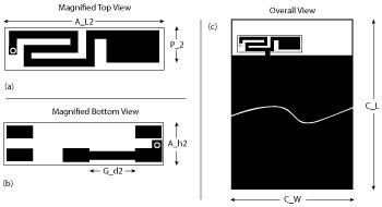
Figure 5 Structure of the chip antenna; top surface (a) bottom surface (b) antenna at an edge of the platform (c).
It is expected that the use of four MIMO antennas will result in higher data transmission and enhanced channel capacity compared to the conventional MIMO architectures that use only two antennas. Figure 7 shows the four-antenna structure with the following dimensions: A_W= 60 mm, A_L= 80 mm, and A_g = 32 mm on the 2 mm-thick substrate of εr = 4.3, loss tangent tanδ= 0.025.
The two ZOR antennas (1 and 2) are placed in the center of the top edge of the handheld platform in Figure 7a. The two chip antennas (3 and 4) are located near the corners of the bottom edge. Their positions are optimal with A_W, A_L, and A_g equal to 60 mm, 80 mm and 32 mm, respectively; with the other geometrical parameters unchanged from the previous design stages. Figure 7b is the simulated return loss for the four antennas showing that they all resonate at 2.4 GHz. Isolation (see Figure 7c) is greater than 10 dB.
Simulated antenna radiation patterns are omni-directional as shown in Figure 8. Radiation efficiency is 47 percent and peak gain is 1.5 dB at the resonant frequency of antennas 1 and 2, which indicates that the radiation efficiency is lower by about 10 percent when compared to their separate designs. Radiation efficiency and peak gain of antennas 3 and 4 are 57 percent and 1.7 dB, respectively. They are acceptable considering the specifications.
MEASUREMENTS
The fabricated antennas are connected to SMA connectors for RF evaluation as shown in Figure 9a. Measured return loss of the individual antennas is slightly shifted from that of the simulation, but the four antennas demonstrate greater than 10 dB return loss at 2.4 GHz (see Figure 9b). The isolation among all the antennas is greater than 10 dB, as well. Figure 9c is the far field pattern of antenna 1 (and antenna 2 by symmetry), and Figure 9d is the far field pattern of antenna 3 (and antenna 2 by symmetry). The peak gains for the four antennas, greater than 1.3 dBi, over almost the omni-directional far field distribution, are suitable for mobile MIMO applications.
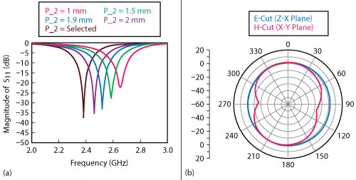
Figure 6 Parametric sweep of the small chip antenna (a) simulated radiation pattern (b).
Conclusion
A compact communication platform with four multiple antennas is designed for LTE MIMO applications. For a higher antenna population in the handset, one pair of small MIMO antennas with a ZOR in-phase electric field distribution is used along with a pair of modified monopole type chip MIMO antennas. The radiator areas are 9 mm × 5.5 mm and 12 mm × 3 mm, respectively. The small size of the radiators plays a critical role in their placement on the top and bottom edges of a realistic handheld device to obtain a low correlation coefficient. It is designed for the 2.4 GHz LTE band, and has useful MIMO performance with the antenna gains greater than 1.3 dBi, and isolation between antennas greater than 10 dB.
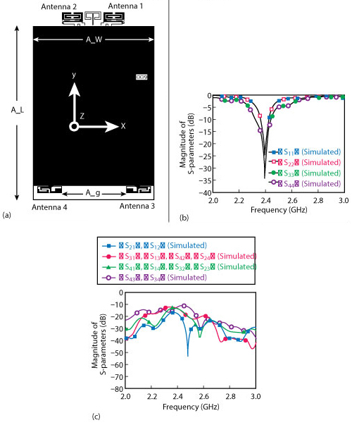
Figure 7 Finalized structure, and simulated frequency responses of the four MIMO antennas; geometry (a) return loss (b) isolation (c).
Acknowledgment
This work was supported by an Incheon National University research grant. S. Kahng, as the lead author, sincerely thanks K. Kahng with AceTechnologies and J.G. Kim with LG Innotek for their help.
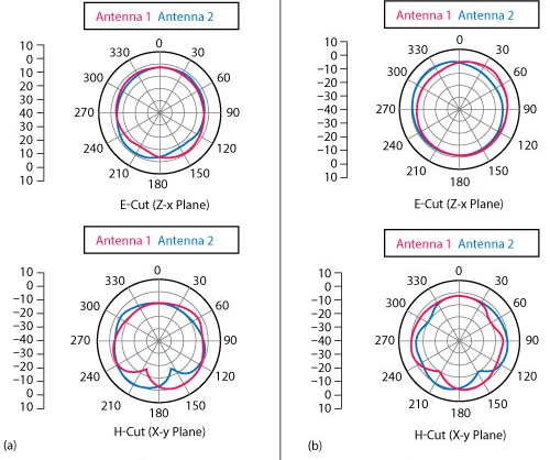
Figure 8 Simulated radiation patterns of the four MIMO Antennas; E- and H-plane cuts of Antennas 1 and 2 (a) E- and H-plane cuts of Antennas 3 and 4 (b).
References
- A. C. K. Mak, C. R. Rowell and R. D. Murch, “Isolation Enhancement Between Two Closely Packed Antennas,” IEEE Transactions on Antennas and Propagation, Vol. 56, No. 11, November 2008, pp. 3411–3419.
- K. Payandehjoo and R. Abhari, “Employing EBG Structures in Multiantenna Systems for Improving Isolation and Diversity Gain,” IEEE Antennas and Wireless Propagation Letters, Vol. 8, November 2009, pp. 1162–1165.
- X. Wang, Z. Feng and K. M. Luk, “Pattern and Polarization Diversity Antenna With High Isolation for Portable Wireless Devices,” IEEE Antennas and Wireless Propagation Letters, Vol. 8, April 2009, pp. 209–211.
- M.S. Sharawi, S.S. Iqbal and Y.S. Faouri, “An 800 MHz 2´1 Compact MIMO Antenna System for LTE Handsets,” IEEE Transactions on Antennas and Propagation, Vol. 59, No. 8, August 2011, pp. 3128–3131.
- R.A. Bhatti, S. Yi and S.O. Park, “Compact Antenna Array With Port Decoupling for LTE-Standardized Mobile Phones,” IEEE Antennas and Wireless Propagation Letters, Vol. 8, January 2009, pp. 1430–1433.
- M.S. Han and J. Choi, “MIMO Antenna Using a Decoupling Network for Next Generation Mobile Application,” International Symposium on Communications and Information Technology, September 2009, pp. 102–105.
- P. Vainikainen, J. Ollikainen, O. Kivekas and I. Kelander, “Resonator-Based Analysis of the Combination of Mobile Handset Antenna and Chassis,” IEEE Transactions on Antennas and Propagation, Vol. 50, No. 10, October 2002, pp. 1433–1444.
- S. Cui, S. X. Gong, Y. Liu, W. Jiang and Y. Guan, “Compact and Low Coupled Monopole Antennas for MIMO System applications,” Journal of Electromagnetic Waves and Applications, Vol. 25, Nos. 5-6, April 2012, pp. 703–712.
- M.S. Sharawi, “Design and Fabrication of a Dual Electrically Small MIMO Antenna System for 4G Terminals,” Proceedings of the German Microwave Conference, March 2011, pp. 67–70.
- M.A. Jan, “A 2×1 Compact Dual Band MIMO Antenna System for Wireless Handheld Terminals,” Proceedings of the IEEE Radio and Wireless Symposium, January 2012, pp. 92–95.
- S. Y. Lin and I. H. Liu, “Small Inverted-U Loop Antenna for MIMO Applications,” Progress in Electromagnetics Research C, Vol. 34, January 2013, pp. 69–84.
- W. Jiang, T. Hong and C. Li, “Dual-Band Coupling Element Based Antennas With High Port Isolation,” Progress In Electromagnetics Research Letters, Vol. 37, 2013, pp. 91–99.
- M. Jusoh, M.F.B. Jamlos, M.R.B. Kamarudin and M.F.B.A. Malek, “A MIMO Antenna Design Challenges for UWB Application,” Progress In Electromagnetics Research B, Vol. 36, 2012, pp. 357–371.
- S. Yoo, K.S. Kahng, S. Kahng, I.K. Yang, J. Ju and J. Anguera, “The Design of CRLH-Based Compact LTE MIMO Antennas,” Proceedings of the European Conference on Antennas and Propagation, March 2012, pp. 26–30.
Hyunsoo Kim received his B.E. degree in February 2014, and is currently pursuing his M.E. degree at Incheon National University in Incheon, Korea. His research fields are microwave engineering, RF components, antennas, wireless power transfer and metamaterials.
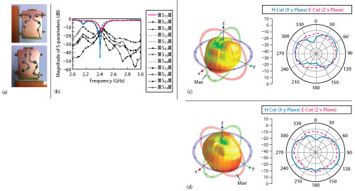
Figure 9 Measured results for the fabricated four MIMO antennas; Photo of the fabricated antennas (a) return loss and interference (b) E- and H-plane beam-patterns for Antennas 1 and 2 (c) E- and H-cut beam-patterns for Antennas 3 and 4 (d).
Sungtek Kahng received his Ph.D. in electronics and communication engineering from Hanyang University, Korea in 2000, with a specialty in radio science and engineering. From 2000 to early 2004, he worked for the Electronics and Telecommunication Research Institute on numerical electromagnetic characterization and developed RF passive components for satellites. In March 2004, he joined the Department of Information and Telecommunication Engineering at Incheon National University where he has continued research on analysis and advanced design methods of microwave components and antennas, including metamaterial technologies, MIMO communication and wireless power transfer for IoT/cyber-physical systems.