Miniature, Low Noise Cryogenic Amplifiers
MITEQ Inc.
Hauppauge, NY
The ability to cause improvement in a GaAs amplifier's noise figure performance by decreasing the base plate temperature has been common knowledge for many years. Various industries and disciplines such as radio astronomy and satellite communications have taken advantage of this concept to increase the sensitivity of their systems. Unfortunately, the major drawbacks to this technology up until now have been size, weight and the support equipment needed to maintain cryogenic temperatures. To address these problems, the JS series miniature, cryogenically cooled, self-contained amplifiers have been developed.
Cryogenic Technology
Most low noise microwave amplifier applications are burdened with the need to operate at or near room temperature. This operating environment may have been influenced in part by the fact that engineers who use the equipment are more comfortable working at +23°C than -100°C. For the low noise GaAs FETs that are used in these amplifiers, the reverse holds true - the colder the FETs are, the better. However, in most cases, amplifier performance is specified at room temperature. Since this is the most convenient way to describe a low noise amplifier, most test environments are defined and compared at room temperature. Specifying amplifier characteristics exclusively at high temperatures is typically avoided and generally included under the umbrella of a maximum noise figure specification. In general, FET noise figures increase and gains decrease as the operating (case) temperatures increase. Conversely, operating at colder temperatures enhances the primary amplifier gain and noise figure characteristics.
Several methods can be utilized to achieve very cold operating temperatures. The most appropriate method for a given application depends on a number of other system or programmatic constraints. Several basic cooling methods lend themselves to amplifiers or other operational electronics, including passive cooling (operating in a cold environment), radiational cooling, using heat pipes to a cold sink, active cooling using liquid nitrogen refrigerant (or some other super-cooled liquid) and electrical junction cooling (a Peltier cooler or the like). Unfortunately, the passive, radiational and heat pipe cooling techniques are not very effective in achieving cryogenic temperatures, and electrical junction cooling is just not efficient. Thus, active cooling is the method of choice.
One easy way to cool electronic components is to bring them in direct contact with another cold object or heat sink. As stated previously, a commonly available source of cooling that normally provides a source of extremely low temperature is liquid nitrogen. Liquid nitrogen or other cryogenic liquids can be used in several ways to provide the desired cooling effect on an amplifier. This cooling can be accomplished by directly immersing the amplifier, mounting the amplifier to a special heat sink in which a cryogenic liquid is circulated or directly attaching the amplifier in some way to a cryogenic heat pump. Obviously, several of these choices can only be implemented easily in a laboratory environment.
In this article amplifier performance is based on FET junction temperatures of 80 to 100 K. These temperatures can be achieved using liquid nitrogen at +77 K (-196°C) or one of the other amplifier cooling techniques listed previously.
Amplifier Design
The actual design of the amplifier required several important decisions to be made up front. It was important to design the RF amplifier's peripheral circuitry to minimize overall net power dissipation - an essential element in achieving the best performance and cooling efficiency. Several other factors also had to be examined to arrive at an optimal solution. First, noting that excess gain increases dissipation, temperature and, ultimately, noise figure, it was necessary to determine the optimum gain to establish the desired system noise figure. Next, the voltage and current supplied to the cooled amplifier stages were minimized. Adequate performance was achievable with as little as 1 V and minimal current. Finally, a thermal package design was developed that fully isolated the active amplifier circuitry from all contact with the associated warmer areas.
It was necessary to maximize the ratio of thermal resistance to input RF losses. The base of the cold spot finger was used as the ground plane and an air line was utilized to transfer the RF energy from the antenna. The thermal resistance for bias connections and connections to any surrounding warm areas was maximized. As a result, the unique design used in the JS series cryogenic amplifiers provides reliable, commercial, easy-to-use units that until just recently were considered laboratory curiosities.
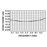
A standard ultra-low noise amplifier design was selected and a way of inserting a probe into the amplifier at a point where a cold spot could be generated was discovered. The first-stage, low noise figure GaAs FETs then were mounted on the cold spot. By carefully maintaining the temperature at this point, noise figures on the order of 0.2 dB (14 K) could be achieved from 3.4 to 4.2 GHz. Once these types of noise figures were achieved and the basic concept was proven, the challenge became how to make the unit reliable, small, light and, ultimately, weatherproof.
In order for the amplifier to be viable, it was necessary to meet all of these criteria, thus allowing the user to mount the amplifier directly on an antenna feed out in the open or fit it into an aircraft or satellite where space and weight are at a premium. Another major concern was the reliability of the cooling apparatus. A Sterling cooler was selected based on size and weight. Basically, a Sterling cooler is a self-contained cryogenic pump that uses compressed helium to obtain cryogenic temperatures. (Until only recently, Sterling coolers were plagued by limited life.) After extensive research and experimentation, a Sterling cooler was selected that met the design's reliability, size and environmental constraints. The unit's reliability data indicated a life expectancy of greater than 30,000 hours. Integrating the cooler with the probe technique enabled all of the design goals to be achieved.
Performance
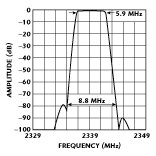
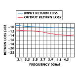
Given the reliable cooler, a life cycle test was performed on the amplifier/cooler combination for repetitive 15-minute cycles (one half-cycle at 80 K and the other at room temperature). Since no failures or degradation occurred in the amplifier/cooler combination after 1500 cycles, it was determined to be reliable. Table 1 lists the specifications for the completed model JCRYO-034042-02-5P amplifier. Figures 1, 2 and 3 show the unit's gain, return loss and noise figure, respectively.
|
Table I | |
|
Frequency range (GHz) |
3.4 to 4.2 |
|
Gain (dB) |
28 min, 30 typ |
|
Noise figure (dB) |
|
|
Input SWR (max) |
2 |
|
Output SWR (max) |
2 |
|
Input/output impedance |
50 |
|
1 dB gain compression at output (dBm) (min) |
+5 |
|
Nominal DC power |
1 V DC at |
|
Input/output connectors |
SMA |
|
Controller power |
12 to 15 V DC at < 1 A |


Conclusion
A miniature, cryogenically cooled, low noise amplifier has been developed that provides system manufacturers with a reliable, easy-to-use solution for improving system sensitivity. The compact unit can be mounted directly at the antenna feed or within an aircraft or satellite where size and weight are critical factors. In addition, ongoing efforts are being made to further improve the amplifier's performance (including methods to increase the thermal resistance and reduce RF losses), and the possible use of indium phosphide transistors is being investigated.
MITEQ Inc.,
Hauppauge, NY
(516) 439-9413.
