
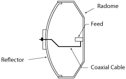
Figure 1 Feed concept.
A low cost circular waveguide feed operates from 17.5 to 19.5 GHz with excellent radiation pattern symmetry, low cross polarization and low back radiation. The design consists of a circular waveguide open end with a quarter-wave choke and a pair of E-plane slots. A dielectric slab is employed to improve impedance matching. The feed is energized with a probe at the end of a coaxial cable instead of a conventional circular or rectangular waveguide. The cable introduces a small loss but significantly simplifies the design and reduces fabrication cost.
In recent years, there has been an increasing demand for low cost 25 to 35 dB gain antennas for point-to-point backhaul communication. The prime focus single reflector antenna is very competitive for this application due to its simplicity and low cost. Feeds for the prime focus reflector usually take the form of self-supporting backfire antennas or waveguide open ends. In the latter case, the waveguide is bent in a gooseneck shape and routed to the transceiver unit at the back of the reflector.
If a waveguide open end feed is used, one can replace the gooseneck waveguide with a coaxial cable by attaching the feed to the inside wall of a suitably dimensioned radome, while accepting a small loss introduced by the coaxial cable. In this article, we describe a high performance and low cost coaxially-fed circular waveguide feed suitable for this application.
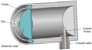
Figure 2 Feed cutaway view.
Feed Design
Characteristics required of a good prime focus feed include radiation pattern rotational symmetry, sharp gain roll-off beyond the reflector illumination angle, low cross polarization, small back radiation and good impedance matching.
Figure 1 shows the concept. The feed is firmly attached to the inside wall of the reflector’s radome. The feed and the radome are dimensioned so that the feed’s phase center is exactly at the reflector’s focal point. The feed is energized with a probe at the end of a coaxial cable, which is then connected to the transceiver unit. Coaxial cables with low loss (e.g., 1.2 dB/m at 18.5 GHz) are commercially available. A reflector of diameter 290 mm gives 35 dB gain at 18.5 GHz with an efficiency of 71.3 percent. In this case, the cable length of suitably bent shape is about 20 cm, which introduces 0.24 dB loss at 18.5 GHz.
Figure 2 shows the feed cross section. It consists of a circular waveguide of a suitable diameter, a quarter-wave choke, a pair of E-plane slots, a dielectric slab for impedance matching and a coaxial probe. The rotational symmetry of the radiation pattern is dependent on the waveguide diameter with 0.9 to 1.2 λ0 being optimum.1 A quarter-wave choke around the aperture wall is added to reduce back radiation as well as to improve the pattern symmetry. A pair of E-plane slots on the “choked” waveguide wall further improves the pattern symmetry;2 however, because the E-plane slots and the choke increase the feed’s reflection coefficient, a dielectric slab (see Figure 3) is added to improve impedance matching.3
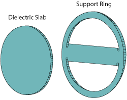
Figure 3 Dielectric insert for impedance matching.
Figure 4 shows the feed’s dimensional parameters. A waveguide diameter of 12 mm (0.74 λ0 at 18.5 GHz) is chosen to obtain the required 12 dB taper at 65 degrees off boresight. A waveguide wall thickness (tw) of 2 mm is suitable to contain a choke with a 1 mm gap. Choke length is optimized for the lowest back radiation over the 17.5 to 19.5 GHz band. The optimum value is found to be 3.7 mm (0.228 λ0 at 18.5 GHz).
Next, a pair of E-plane slots (two rectangular slots 180 degrees apart) are placed so that the aperture’s electric field is formed across the slot gap of dimension (hs). The E-plane slots equalize E- and H-plane patterns by virtually increasing the aperture width in the H plane. The width and length of E-plane slots are optimized for best pattern symmetry: slot length lch = 3.7 mm and slot gap hs = 1.88 mm.
The circular waveguide’s open end of 0.74 λ0 diameter does not provide a good impedance match. Further mismatch is caused by the choke and E-plane slots. The match is improved by placing a dielectric slab with thickness (td1) of 0.5 mm at the base of the choke inside the waveguide. Polycarbonate (PC) with a dielectric constant of 2.7 and loss tangent of 0.002 is used as the dielectric material. The dielectric insert in Figure 3 is composed of two parts, a circular slab for matching and a support ring for attaching the slab to the waveguide. The total thickness td of the dielectric insert is 1 mm, including the support ring.
The thickness and location of the dielectric insert are very important in obtaining a good impedance match. The support ring is inserted at the base of the choke gap and then securely bonded so that it does not move or rotate. The combined structure of the slab and the ring is precisely machined. The quarter-wave choke, E-plane slots and dielectric matching structure are all designed for excitation in the dominant TE11 mode.
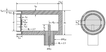
Figure 4 Feed dimensional parameters.
The final design step is optimization of the coaxial probe. The probe diameter is 1.28 mm in an SMA connector. The position from the waveguide back short (dp) and the length lp of the probe are optimized using Microwave Studio™ to obtain the lowest reflection coefficient over the 17.5 to 19.5 GHz band. This results in lp = 3.4 mm and dp = 6.1 mm. The total length of the feed is l + tw = 30 + 2 = 32 mm.
Figure 5 shows the feed’s E-plane, H-plane and cross-polarized radiation patterns at 18.5 GHz. It has excellent pattern symmetry up to 90 degrees off boresight. Maximum gain is 10 dB with a taper of 12 dB at 65 degrees from the boresight (θ= 65 degrees). At 17.5 GHz and 19.5 GHz, the E- and H-plane gain difference is 1.2 dB and 1.6 dB, and at θ= 65 degrees and maximum gain is 9.6 dB and 10.5 dB, respectively.
The maximum level of the cross polarization in the 45-degree plane is about -27 dB relative to the maximum co-polarized gain. The phase center is 0.6 mm away from the aperture plane toward the reflector surface. With the coordinate origin at the phase center, the far field phase deviations over 0 to 65 degrees off boresight are 1.1 degrees and 4.7 degrees in the E- and H-planes, respectively.
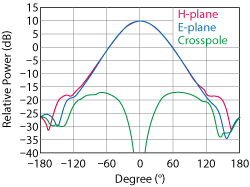
Figure 5 Simulated far field gain patterns.
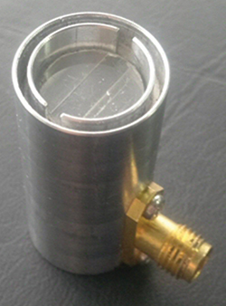
Figure 6 Fabricated feed.
When feeding a 290 mm diameter reflector with F/D = 0.392, the reflector has 35 dB gain with 71.3 percent efficiency, 3 dB beamwidths of 3.94 degrees in the E-plane and 3.84 degrees in the H-plane and sidelobe levels of -26 dB in the E-plane and -23 dB in the H-plane, respectively.
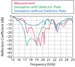
Figure 7 Reflection coefficient of the fabricated feed.
Fabrication and Measurement
Figure 6 shows the fabricated feed antenna. The circular waveguide, choke and E-plane slots are machined out of an aluminum block. A solid piece of polycarbonate material is machined to the dimensions of the dielectric matching plate. The probe of the designed length is placed at the proper position using a panel-mount type SMA connector.
The measured reflection coefficient of the feed is less than -10 dB over 17 to 21 GHz (see Figure 7). The improvement in the impedance matching by the dielectric plate can clearly be seen. Figure 8 shows the E-plane gain pattern of the fabricated feed at 18.5 GHz, which agrees well with the simulation. The H-plane gain pattern exhibits similar agreement.
Conclusion
A low cost, high performance feed for use in prime focus reflector antennas consists of a circular waveguide, a quarter-wave choke, a pair of slots on the choked wall and a coaxial probe. The feed is connected directly to a coaxial cable that is routed to the transceiver unit at the back of the reflector. The feed demonstrates pattern symmetry, low cross polarization, low back radiation and good impedance matching. Compared to the conventional goose-neck type feed, it has an additional 0.2 to 0.3 dB loss due to the coaxial cable. This is offset by the simplicity of connecting the feed to the transceiver unit.
Acknowledgment
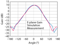
Figure 8 E-plane gain pattern of the fabricated feed.
This work was supported by the Human Resources Development of the Korea Institute of Energy Technology Evaluation and Planning (KETEP) grant funded by the Korean government Ministry of Trade, Industry & Energy (No. 2014020901).
References
- A.D. Olver, P.J.B. Clarricoats, A.A. Kishk and L. Shafai, “Microwave Horns and Feeds,” IEEE, New York, 1994.
- L. Shafai, “Broadening of Primary Feed Patterns by Small E-Plane Slots,” Electronic Letters, Vol. 13, No. 4, February 1977, pp. 102–103.
- J.J. Lee and R.S. Chu, “Aperture Matching of a Dielectric Loaded Circular Waveguide Element Array,” IEEE Transactions on Antennas and Propagation, Vol. 37, No. 3, March 1989, pp. 395–399.