
Typically, an internal antenna may be custom designed and integrated into a radio’s printed wiring board (PWB) or case and implemented as a separate component. Matching elements are then attached to the PWB or remotely connected to the radio with a cable and connectors. These alternatives suffer from inflexibility and poor economy. A new hexaband cellular antenna that is partly integrated into the PWB and compatible with mass production has been designed and tested. The new design offers the benefits of customization and high volume production without requiring a separate matching network.
Figure 1 Typical matching network block diagram (a) and layout (b) recommended by an antenna manufacturer.1
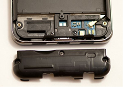
Figure 2 Antenna integrated into the package.2
There is a trend toward connecting machines to the Internet and to each other wirelessly, using radios that have been integrated into the machine’s packaging. Equipment manufacturers, wanting to provide a product that is generally serviceable at a reasonable cost, desire that their products, in general, and particularly the installed antenna, operates as flexibly and economically as possible. In addition to being capable of receiving and transmitting wireless information the antenna must be designed to be compatible with the radio equipment to which it is connected. It is said that the antenna and radio equipment must be “matched.”
The essential characteristic of being matched is that information will be passed from antenna to radio and from radio to antenna without reflection of the electromagnetic waves upon which the information is superposed. One must ensure that all elements are matched to one another, by selecting and inserting extra circuit elements (see Figure 1) or by modifying the design of the elements. This process is not too difficult for the non-radiating elements of the signal path, because these elements are relatively immune to influence by other system changes, such as the package that contains the radio equipment. Once the circuit connections to and from the non-radiating elements in the signal path are quantified and have been matched, no further tuning is usually necessary. For example, a system designer usually specifies that an amplifier, filter, switch, mixer, connectors, cables and other elements all match when incorporated into a system. The vendors of these elements are able to provide these components to many system designers for integration into different systems, as long as the system matching requirements are similarly defined.
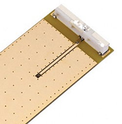
Figure 3 Discrete antenna mounted to a PWB.3
However this is not necessarily the case with the antenna. The antenna, by virtue of its unique role in the transmission and reception of information-bearing waves, is susceptible to the influence of local but non-connected elements, such as the package that contains the antenna or the PWB that supports other system components. One way to deal with this problem is to place the antenna far away from anything that might influence its characteristics and connect it to the radio with a cable. Another approach is for the antenna manufacturer to precisely define the characteristics of the package that houses the antenna. Unfortunately, forcing these definitions on the equipment manufactures is not “flexible.” A third way to deal with the influence of non-connected elements on the antenna is to custom tune the antenna for each situation — every possible style of packaging, for example. This requires designing different antennas for different packages, which is not economical unless the radio equipment will be manufactured in large quantities.
There is a need for an antenna that is customizable to a particular installation at minimum cost and without the need for additional matching elements to be purchased and installed into the radio. An antenna may be incorporated into a packaged radio by integrating it into either the PWB or the radio package (see Figure 2). In this instance, the antenna cost is low because the PWB and package have to be manufactured anyway. But the antenna’s performance may be compromised because the materials used to manufacture the PWB or package are not suited to the requirements of the antenna design. The main drawback is that the cost of custom designing an integrated antenna is high. Another approach is to design the antenna as a discrete element that is attached or connected to the PWB (see Figure 3). This usually results in better performance at higher cost. The antenna cost is slightly higher, and it typically requires a custom matching network which contributes to the total manufacturing cost of the antenna. The design cost is lower but now includes the matching network. A third option to incorporate an antenna into a packaged radio is by providing a short “pigtail” with the antenna (see Figure 4). This method allows the antenna to be placed away from the PWB, allowing more design flexibility; however, the cost of the pigtail, a board connector and the inevitable matching network contribute to the antenna cost.
Figure 4 Discrete antenna connected to the PWB with a pigtail.4
Multiband Hybrid Design
In the proposed design, some of the antenna’s radiating functionality is designed into the PWB, with the remainder designed into a mass-produced element that is attached to the PWB during radio assembly. The radiating functionality is shared between an integrated, customized PWB and the mass-produced portion — a composite of the two.
Prior designs divided the antenna into a PWB portion that operates in one sub-band and an attached portion that operates in another sub-band, i.e., in an uncooperative manner. With this design approach, both the PWB and the attached portion operate cooperatively over the entire frequency range of the design. Tuning is still required for the antenna to be matched to the packaged radio, yet all the needed tuning features are incorporated into the “free” PWB portion (see Figure 5). The PWB may be tuned at one or more separate locations for optimum matching, while the attached portion is designed to be economically mass produced while providing the improved performance associated with the discrete antennas of prior art. The hexaband embodiment is able to work in a variety of packaged cellular radios because it is a composite of a mass-produced portion that radiates efficiently, like the typical antenna mounted on a PWB, and a highly customizable, tunable portion that is essentially free of manufacturing cost, like the typical antenna that is integrated into the PWB.
The applied, mass-produced hardware shown in Figure 5 was realized from a metal stamping, although it may also be fabricated from metallization applied to a supporting structure made from ceramic, plastic, glass or the like. The mass-produced segment may be self-supporting or supported by a non-metallic structure. The key feature of the design is that the antenna’s functionality is hybridized, with tunable matching functionality incorporated into the integrated PWB and radiating functionality shared by the PWB and the mass-produced element.
Figure 5 Proposed design is a composite of a tunable, low cost, integrated portion and an efficiently radiating mass-produced portion.
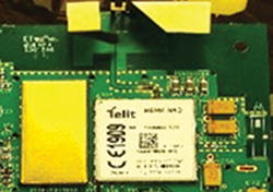
Figure 6 Assembled prototype of the hybrid antenna.
Performance
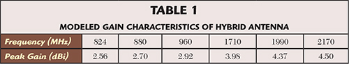
To gauge the performance of the hybrid design, a “real” board layout and components (see Figure 6) were tested. The grounded coplanar waveguide RF trace was interrupted at the radio module’s RF pin, and a backside SMA wave launcher was soldered to the modified board. The measured return loss of five prototypes is shown in Figure 7. The modeled peak gains of the new design are presented in Table 1, and the typical simulated antenna radiation patterns are presented in Figure 8.
During simulation, it was noted that adding a shunt inductor to the design improved the return loss of the upper frequency range to -15 dB. This strategy would have improved the input match but at the expense of ohmic loss in the inductor and added manufacturing cost. The measured return loss of the baseline design at the upper frequency was -7.5 dB (0.178 reflection coefficient). If we improve the return loss to -15 dB (0.032 reflection coefficient) with the addition of the shunt inductor, the additional power delivered to the antenna would potentially be 10×log10(1 - 0.146) ≈ 0.7 dB. But if we allow for the insertion loss of a lumped inductor, say 0.2 dB, the potential benefit of improving the match amounts to less than a half decibel at the matched frequency. For many applications, this slight improvement in match does not justify the additional cost and complexity of adding the matching element to the bill of materials.
Figure 7 Return loss of five samples compared to the simulation.
CONCLUSION
A new hexaband cellular antenna partly integrated into the PWB and partly a massed produced component has been designed and tested. The new design demonstrates the benefits of both customization and high volume production, without the need for a separate matching network. Measured and modeled data of the prototypes are in good agreement.
ACKNOWLEDGMENT
The assistance of the staff at the University of Arkansas High Density Electronics Center (HiDEC) is greatly appreciated in building and testing the prototypes.
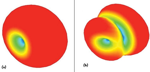
Figure 8 Typical radiation pattern of the hybrid antenna in the 824 to 960 MHz (a) and 1710 to 2170 MHz (b) cellular bands.
References
- “PA.25.A,” Application Note (APN-11-8-002.B).pdf, Accessed May 17, 2015, www.taoglas.com/images/product_images/original_images/PA.25.A%20Application%20Note%20%28APN-11-8-002.B%29.pdf, p. 23.
- “Baseband and Disassembling the LG Optimus 2X - LG Optimus 2X & NVIDIA Tegra 2 Review: The First Dual-Core Smartphone,” Accessed May 17, 2015, www.anandtech.com/show/4144/lg-optimus-2x-nvidia-tegra-2-review-the-first-dual-core-smartphone/9.
- “PAD.25 Evaluation Board,” Accessed May 25, 2015, www.digikey.com/catalog/en/partgroup/pad-25-evaluation-board/31496.
- Embedded_LTE_1002289_20150213.pdf, Accessed May 17, 2015. www.ethertronics.com/files/1414/2386/9980/Embedded_LTE_1002289_20150213.pdf, p. 2.