
Experimental Adaptive Nulling with a Genetic Algorithm
An adaptive antenna system rejects interference by placing a null in its antenna pattern in the direction of the interfering source. A single-element antenna needs at least one other element or some scattering object to form a null. Thus, adaptive antennas are often synonymous with adaptive arrays. Adaptive antennas are a subset of smart antennas1 and have received considerable interest in the recent wireless revolution.2 This article describes the application of a genetic algorithm with an experimental antenna for placing a null in the direction of an interference source.
Randy Haupt
University of Nevada, Electrical Engineering Department
Reno, NV
Hugh Southall
ARINC Inc.
Lexington, MA
Most approaches to nulling using adaptive antennas fall into four categories. The first category requires a receiver at each array element. This approach forms a correlation matrix from the signals at each element and inverts the matrix to determine the optimum weights that maximize the signal-to-signal plus interference ratio (SNIR). Many variations to this approach exist, but they all require knowledge of the signal received at each element. Multiple receivers are expensive and the receivers must be calibrated continuously. Therefore, this approach is impractical for large arrays.
A second category of nulling assumes the interference location is known and the characteristics of the attenuators and/or phase shifters are accurately predictable. Given this information, weights that form the desired null(s) are derived by computer mathematically and implemented on the array. Such an approach is impractical because the location of the interfering signal is not likely to be known. Also, the array weights have tolerances and errors that prevent their exact specification.3
A third category of adaptive nulling randomly guesses at possible amplitude and phase settings for the antenna array. This Monte Carlo approach to adaptive nulling is time consuming and usually not practical to implement for real-time systems.4
A final approach implements a numerical optimization algorithm to minimize the total output power of the array. This approach typically forms a gradient vector by perturbing the phase and/or amplitude settings of the elements to determine the weights that minimize the total output power.5 These approaches are slow and often get stuck in local minima.
The approach presented in this article uses a genetic algorithm to determine the phase and amplitude weights that minimize the total output power of the array. The desired signal is assumed to enter the mainbeam and interfering signals are assumed to enter the sidelobes. The genetic algorithm is implemented on a PC that controls the eight-element cylindrical array. An adaptive, phase-only genetic algorithm applied to a computer model of a linear array has been reported previously.6 This article extends the previous work to amplitude and phase nulling on an experimental cylindrical antenna array.
The Experimental PHASED-Array Antenna
The experimental phased-array antenna was developed by the Air Force Research Laboratory (AFRL) at Hanscom Air Force Base, MA for experiments with artificial intelligence techniques such as neural networks and genetic algorithms.7,8 The antenna consists of 128 vertical columns (16 dipoles per  column) equally spaced around a cylinder that is 41 inches in diameter, as shown in Figure 1 . The outputs of the 16 dipoles are combined to form a fixed-elevation beam with a peak gain 3° above horizontal. Only eight columns of elements are active in this application. The eight-element sector is 22.5° in arc (1/16 of the cylinder), with the eight elements spaced approximately one inch (or 0.42 l) apart at the center frequency of 5 GHz.
A unique feature of this antenna is that either all the active elements can be connected to the power combiner at once (that is, a standard corporate-fed phased array) or one element at a time can be connected to the receiver while the others are terminated in a matched load. Connecting one element at a time to the receiver simulates a digital beamforming antenna. In this application, all eight elements are connected in a corporate feed. Thus, the adaptive element only has access to the total received power of the array and not the amplitude and phase of the signals at each of the elements.
 The output of each element is connected to a single channel containing an eight-bit phase shifter and eight-bit attenuator. All eight channels are combined in a power combiner whose output goes to a phase/amplitude receiver. Figure 2 shows one of the two phase shifter/attenuator banks. The phase shifters have eight bits ranging from 1.4° to 180°. The attenuators are linear over an 80 dB range with the least significant bit having an attenuation of 0.3125 dB. The antenna must be calibrated to form a main beam. In this case, the calibration (or quiescent) pattern is a 25 dB n_ = 3 Taylor taper. Phase shifters are adjusted to compensate for the curvature of the array and unequal path lengths through the feed.
Figure 3 shows the antenna mounted in the anechoic chamber at AFRL. The  chamber measures 72' ¥ 36' ¥ 36'. A horn antenna serves as the feed and is located 47' from the antenna. The source is CW and the phase/amplitude receiver is a model SA 1780. The measurements have a dynamic range of approximately 50 dB. Thus, nulls that are 50 dB below the peak of the main beam are the best that can be discerned. Phase shifters and attenuators are controlled with an HT Basic program from a PC.
The Adaptive Genetic Algorithm
A genetic algorithm is a computer program that determines an optimum solution by simulating genetics and natural selection. In this application, the phase shifter settings evolve until the antenna pattern has a null in the direction of the jammer. A genetic algorithm was chosen for this application because it is an efficient method for searching an extremely large, discrete area of phase and amplitude settings for the minimum array output power. An adaptive array has 2NP possible phase and attenuator settings (N = number of elements and P = number of attenuator and phase shifter bits used for nulling), many that correspond to local minima in the total power output. Such a large number of settings (and local minima) make random search and gradient-based algorithms impractical to use.
An adaptive algorithm modifies the quantized phase and amplitude weights based on the total output power of the array. The goal of the adaptive array is to minimize total output power, which consists of the interference signal and possibly the desired signal. If no interference was present, the algorithm would minimize the desired signal. This dilemma was solved by using a limited number of digital phase shifter and attenuator bits. Using the lower order bits for nulling allows formation of nulls in the sidelobes without significant impact on the main beam (desired signal). The computer generates an amplitude and phase setting  and sends this setting to the array. Next, the output power associated with the setting is read and stored in the computer with the adapted weights. As noted previously, the least significant bits are used for nulling so the main beam is not nulled, and the desired signal receives minimal attenuation. Figure 4 shows a model of the adaptive antenna array.
 Figure 5 shows a flow chart of the adaptive amplitude/phase genetic algorithm, which begins with an initial population consisting of a matrix filled with random ones and zeros. Each row of the matrix (chromosome) consists of the nulling bits for each element placed side by side. (There are NP columns and M rows.) The output power corresponding to each chromosome in the matrix is measured and placed in a vector.
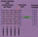 Figure 6 shows a simple example for a five-element array. Here, two bits are used for phase control and two bits for attenuator control, resulting in four bits per element in each chromosome. The nulling bits are sent to each array and an output power is measured for each chromosome. M is relatively small (between 12 and 20 performed well).
The output power and corresponding chromosomes are ranked from lowest to highest output power. Next, the bottom 50 percent of the chromosomes are discarded because they have the greatest output power. The algorithm generates new chromosomes to replace the discarded bottom 50 percent, as shown in Figure 7 . The top 50 percent of the chromosomes are mated pair wise, that is, one to two, three to four and so forth. This procedure produces the same number of children as parents and is sufficient to replenish the discarded bottom 50 percent of the chromosomes. A random point is selected and bits to the right of the random point are swapped to form two new chromosomes. These new chromosomes are placed in the matrix to replace two settings that were discarded and their output powers are measured.
When enough new chromosomes are created to replace those discarded, the chromosomes are ranked and the process repeated. A small number (less than one percent) of the nulling bits in the matrix are mutated-- switched randomly from a one to zero or vise versa. The best phase setting is not altered. These mutations allow the algorithm to try new areas of the search space while still converging on a solution. More general descriptions of genetic algorithms can be found in the literature.9,10
Experimental Results
 The jammer was a CW source at 5 GHz. Only the four least significant bits of both the eight-bit phase shifters and attenuators were used. Figure 8 shows the adapted pattern superimposed on the quiescent pattern. The main beam is steered to broadside. The null at 45° is -56 dB and approximately 31 dB below the quiescent pattern. Since this null is below the noise floor of the measurement system, the algorithm cannot improve any further.
Figure 9 shows the convergence of the genetic algorithm for a population size of 16 chromosomes. Note that the algorithm converged in only two iterations (or less than 24 power measurements). The green line represents the null depth of the best chromosome and the orange line represents the average null depth for the entire population (16 chromosomes). In this case, the average plot is important because the antenna receives signals constantly so a low average power is important for improving the SNIR. Only one chromosome in each generation is mutated (a mutation rate of 0.1 percent).
The adapted pattern has a large sidelobe at -45° in addition to putting a null at +45°. This phenomenon is characteristic of phase-only nulling.11 Amplitude weighting was used in this experiment, but the effects of the amplitude weights were so small that they can be ignored. Theory predicts that the increase in the symmetric sidelobe should be approximately 3 dB. The data plot shows an increase of approximately 14 dB. The sidelobes on either side of the adaptive null also increased.
 Figure 10 shows the adapted pattern for a null at 28.5° superimposed on the quiescent pattern. The main beam is steered to broadside. The null depth is -49.4 dB or 22 dB below the quiescent pattern. The adapted pattern raised the sidelobe at -28.5° by approximately 10 dB. The sidelobe at 75° increased approximately 18 dB.
Figure 11 shows the convergence of the genetic algorithm for a population size  of 16 chromosomes. The null was formed in four iterations or 40 power measurements. The green line represents the null depth of the best chromosome and the orange line represents the average null depth for the entire population (16 chromosomes). The average sidelobe level for the 16 chromosomes of the final population is -34.8 dB.
Conclusion
The genetic algorithm quickly placed nulls in the array antenna pattern without resorting to a receiver at each array element. Limiting the nulling controls to a few least significant bits of the phase shifters and attenuators allowed for better control of the antenna pattern as well as improved algorithm convergence.
Acknowledgment
This work was funded by the US Air Force under AFRL Contract F30602-98-C-0033. The authors wish to thank Michael Beaudet and Ed Martin for the measurement support.
References
1. D. Robbins and M.G. Amin, "Cellular Mobile Radio Communication Channels in View of Smart Antenna Systems," Microwave Journal, Vol. 41, No. 4, April 1998, pp. 74-86.
2. L.C. Godara, "Applications of Antenna Arrays to Mobile Communications, Part I: Performance Improvement, Feasibility and System Considerations," IEEE Proceedings, Vol. 85, No. 7, July 1997, pp. 1029-1060.
3. H. Steyskal, "Simple Method for Pattern Nulling by Phase Perturbation," IEEE AP-S Transactions, Vol. 31, No. 1, January 1983, pp. 163-166.
4. R.A. Monzingo and T.W. Miller, Introduction to Adaptive Antennas, Wiley, New York, NY, 1980.
5. R.L. Haupt, "Adaptive Nulling in Monopulse Antennas," IEEE AP-S Transactions, Vol. AP-36, No. 1, January 1988.
6. R.L. Haupt, "Phase-only Adaptive Nulling with Genetic Algorithms," IEEE AP-S Transactions, Vol. 45, May 1997.
7. H.L. Southall, J.A. Simmers and T.H. O'Donnell, "Direction Finding in Phased Arrays with a Neural Network Beamformer," IEEE AP-S Transactions, Vol. 43, No. 12, December 1997, pp. 1369-1374.
8. H.L. Southall, S. Santarelli and E. Martin, "Neural Network Beam-steering for Phased Array Antennas," Proceedings of the 1995 Antenna Applications Symposium, Robert Allerton Park, University of Illinois, Champaign-Urbana, IL, September 1995.
9. J.H. Holland, "Genetic Algorithms," Sci. Amer., July 1992, pp. 66-72.
10. R.L. Haupt and Sue Ellen Haupt, Practical Genetic Algorithms, John Wiley & Sons, New York, NY, 1998.
11. R.A. Shore, "Nulling at Symmetric Pattern Location with Phase-only Weight Control," IEEE AP-S Transactions, Vol. 32, No. 5, May 1984, pp. 530-533.
Randy L. Haupt received his BSEE from the US Air Force (USAF) Academy, his MS in engineering management from Western New England College and his PhD from the University of Michigan. His work experience includes positions as an electrical engineer for the OTH-B Radar Program Office and an antenna research engineer for Rome Air Development Center (both at Hanscom Air Force Base, MA). Haupt recently retired from the USAF as a lieutenant colonel and professor of electrical engineering at the USAF Academy. Currently, he is professor and chair of electrical engineering at the University of Nevada at Reno.
Hugh L. Southall received his BS in electrical engineering from the University of Texas at Arlington in 1968 and his MSEE and PhD in electrical engineering from Texas Tech in 1970 and 1975, respectively. He is a retired US Air Force officer currently employed by ARINC Inc. at the Air Force Office at MIT Lincoln Laboratory, Hanscom Air Force Base, MA. He is also a part-time lecturer at Northeastern University. His current research area is antenna systems. Southall is an IEEE senior member and a member of Tau Beta Pi and Eta Kappa Nu.