
With release 12, the third generation partnership project (3GPP) has taken on the challenge to enhance the LTE specifications to support features essential for critical communication systems. The two initial features to be standardized are LTE device-to-device (D2D) proximity services (ProSe) and group call system enablers (GCSE) for LTE. Both features are adding quite some complexity to the standard, including new types of signals with specific characteristics that have to be transmitted and amplified by the handset’s power amplifier.
As these signals have a higher peak-to-average power ratio (PAPR) than the standard LTE uplink signals (such as PUCCH, PUSCH, DMRS), it is important for companies who design power amplifiers to verify that their products still comply with the standard and that recently developed digital predistortion (DPD) algorithms and shaping tables for envelope tracking (ET) are still valid. This article discusses the fundamentals of device-to-device communication, the newly introduced synchronization signals, their characteristics and how to ensure that the power amplifier is still working within the specification.
How LTE D2D ProSe Works
The objective for LTE D2D ProSe is to allow devices in close proximity to detect each other and to communicate directly. For this purpose, two functionalities have been standardized. First, direct discovery allows for a device to either announce or to monitor information of interest upon authorization and provisioning from the serving LTE network. Second, direct communication enables two or more devices to establish group communication. The latter is only intended for non-commercial public safety applications.
While integrating these two features into the standard, 3GPP (the standardization body behind LTE/LTE-Advanced) defined three different coverage scenarios: the ‘in-coverage’ case, where two devices are served by a LTE base station; the ‘partial coverage’ case, where only one device is served by a base station and the second one is ‘out-of-coverage’; and the ‘out-of-coverage’ case, where both devices are not in range of a base station. These three scenarios provide different challenges when realizing direct discovery and direct communication.
The first challenge is to define when and on what resources a device will be allowed to transmit and receive. Before taking on this challenge, 3GPP made a fundamental decision by deciding to (re)use the LTE uplink structure as much as possible for LTE D2D ProSe. This means that the underlying access scheme is single-carrier frequency division multiple access (SC-FDMA), and a device using direct discovery or direct communication transmits and receives using uplink frequencies for FDD-based systems and uplink subframes in TD-LTE.
The resource pools for transmission and reception for both direct discovery and direct communication are broadcast by two newly introduced system information blocks (SIB), Type 18 and 19, respectively. A device that is not served by the LTE network and found to be ‘out-of-coverage’ will use relevant parameters that were either stored on the UICC card placed in the device or that are hard-coded on the device itself.
Synchronization in LTE D2D ProSe
The prerequisite before any communication can happen for all scenarios – in-coverage, partial coverage or out-of-coverage – is that the transmitting device and the receiving device have to be time-aligned. In standard LTE, synchronization is typically established based on synchronization signals that are embedded in the downlink signal provided by the LTE base station. There are two signals designed for this purpose: the primary and secondary synchronization signals (PSS, SSS). These signals are transmitted every 5 ms, twice per 10 ms radio frame. With the help of these signals a device gets frame synchronized and identifies the physical cell identity (PCI) of the serving cell. This identity is used to determine the mapping of the reference signals, which allows the device to fully synchronize in time and frequency.
Figure 1 Synchronization flowchart for direct communication.
Figure 2 Synchronization subframe for direct communication for normal cyclic prefix.
Obviously, in the out-of-coverage case, there is no base station. Thus, no signals exist with which a device can properly synchronize. In such a case, one of the devices should assume this role and provide synchronization signals for other devices. Also, in the in-coverage and, especially, the partial coverage scenario, there might be the necessity for a device to transmit synchronization signals, even if it is considered under coverage. Therefore, 3GPP has defined a ‘step-by-step’ approach that a device undergoes to determine whether or not to transmit the newly defined synchronization signals, called sidelink synchronization signals (SLSS). Figure 1 shows the related flow chart for direct communication. For direct discovery, the device would only transmit SLSS.
It is decisive whether the device has a passive (RRC_IDLE) or an active (RRC_CONNECTED) connection with the network. In the latter case, the network will inform the device via a signaling message to start transmission of SLSS and the newly introduced physical sidelink broadcast channel (PSBCH). In case of idle mode, the device first needs to determine if it is in-coverage by carrying out quality measurements on the downlink reference signals (reference signal received power, RSRP). If the measurement result is above a certain threshold, the device uses the synchronization signals provided by the base station. If not, it starts transmitting SLSS and PSBCH. The threshold is configurable and provided via system information to the device.
In the case where the RSRP measurement is below another threshold that is pre-configured in the device, the terminal considers itself out-of-coverage and starts looking for the SLSS issued by another device. If it detects these types of signals, the device has to carry out newly defined quality measurements known as sidelink reference signal received power (S-RSRP). The measurements are carried out on the demodulation reference signals (DMRS) embedded in the synchronization subframe (see Figure 2). If the result is above a pre-configured limit, the terminal synchronizes to the SLSS issued by that device, otherwise it becomes a so called ‘synchronization source’ and starts transmitting SLSS and PSBCH itself.
Figure 3 PAPR (a) and CM (b) values for the SSSS.
Architecture of SLSS and Subframe Mapping
Similar to the downlink synchronization signal architecture, the SLSS are comprised of two sequences: the primary sidelink synchronization signal (PSSS) and the secondary sidelink synchronization signal (SSSS). The latter is identical to the secondary synchronization signal used in the downlink. Also the PSSS relies on the fundamentals of the PSS in downlink. It is still based on a constant amplitude zero auto-correlation (CAZAC) sequence, specifically a Zadoff-Chu sequence.'
However, for the purpose of LTE D2D ProSe, two new root indices were introduced: 26 and 37. The PSSS is therefore defined by two different sequences, compared to the three sequences in downlink for traditional LTE. Similar to the PCI in downlink, PSSS and SSSS are used to define the so called sidelink identity (N or SLSSID), that ranges from 0 to 335. The number of possible N is divided into two sets, where 0 to 167 are used for the in-coverage case and 168 to 335 for the out-of-coverage case. For the latter, the PSSS is generated using root index 37; in all other cases root index 26 is used. This enables a device which uses these SLSS as a reference to align its receiver to determine if the generating device (i.e., synchronization source or reference UE) is itself in-coverage or out-of-coverage.
Likewise, in downlink the SLSS are mapped to the six inner resource blocks around the carrier frequency. Similar to the downlink synchronization signals, SLSS occupy 62 of 72 available subcarriers. For the case of normal cyclic prefix, PSSS occupies SC-FDMA symbols #1 and #2 whereas SSSS is mapped to symbols #11 and #12. Symbols #3 and #10 carry the demodulation reference signals (DMRS) that were mentioned earlier. The last symbol is used as a guard symbol. The remaining symbols are utilized by the physical sidelink broadcast channel. Figure 2 visualizes the described subframe mapping.
The radio frame where a terminal starts transmitting SLSS and PSBCH in subframe 0 and 5 is configured by higher layers by means of providing the system frame number (SFN). The periodicity of SLSS, PSBCH is 40 ms, which has been defined to save battery power.
An interesting aspect is to examine the characteristic of these newly defined signals – they have to be generated, amplified and transmitted by a device that either has received the task by the network or has determined to transmit those signals following the flow chart outlined in Figure 1. Of particular interest is the SSSS. As it can be derived from simulations shown in Figure 3, the PAPR and cubic m (CM) for SSSS varies greatly over the potential sidelink identities.
Signal Level Challenges
As shown in Figure 3, there are cases for both in-coverage and out-of-coverage where the SSSS exceeds a PAPR of 10.5 and where the signal has a CM of up to 13 dB. This is even the case when SC-FDMA is used as the underlying multiple access scheme, which was introduced to overcome the unfavorable characteristics of a multicarrier scheme like OFDM. A high PAPR and CM is a tough design challenge for component manufacturers, especially handset power amplifiers. At this point, 3GPP has not decided on a way to overcome this challenge. Two options are in place: the first, a power back-off of up to 4 dB for SSSS while transmitting on maximum power. The value is currently discussed in 3GPP’s relevant working groups RAN 4 and 5. The second option is restricting possible values that show a high PAPR and CM.
Figure 4 CCDF measurement to determine PAPR for SLSSID = 288, made using the Rohde & Schwarz FSW signal and spectrum analyzer.
However, this is currently not foreseen by 3GPP. Consequently, it is up to the respective network operator that deploys LTE D2D ProSe, direct discovery and/or direct communication, which SLSSID is being used. Depending on the coverage state (in-coverage or out-of-coverage), a pool of identities might be made available to the device as part of the broadcast system information. Here, the operator can influence the selected SLSSID. However, different circumstances exist for the out-of-coverage situation. It matters whether the terminal synchronizes to a device that sends out SLSS and this particular device is in-coverage or whether the device in question is not synchronizing to another terminal.
For the latter case, the device will randomly select an identity out of the available set of SLSSID’s for the out-of-coverage situation (168 to 335) by applying a uniform distribution. This means a terminal can pick an SLSSID and thus an SSSS which has a high PAPR and CM. Such an SLSSID could be 288, for example (compare Figure 3). Figure 4 shows the CCDF to determine the PAPR for a synchronization subframe with all relevant signals – PSBCH, PSSS, DMRS and SSSS that form a SLSSID of 288. This statistical measurement was carried out using a signal and spectrum analyzer.
PA Considerations
The new signals provide a new, challenging task to companies that design and manufacture components for modern handsets and tablets, in particular handset power amplifiers. Adequate test tools are required to test and verify that current and future products still fulfill the standard’s requirements such as error vector magnitude (EVM) and adjacent leakage power ratio (ACLR) or spectrum emission mask (SEM), while transmitting signals with a high PAPR and CM.
Figure 5 Test setup for DPD and ET using Rohde & Schwarz SMW200A vector signal generator (left) and FSW signal and spectrum analyzer (right).
While the procedures and test tolerances to carry out the measurements for this new set of signals are still being discussed by 3GPP, the design engineer can already start to validate that recently developed DPD models and ET algorithms are still applicable for these signals on existing products or products currently under development. DPD and ET have been recently introduced to power amplifiers powering modern smartphones and tablets to optimize battery life and power consumption.
The same goals apply to a device that operates in direct mode using direct communication. One possible setup to carry out DPD and ET measurements is a vector signal generator in interaction with a signal and spectrum analyzer. The setup and required software options are shown in Figure 5.
In this setup, the signal generator provides the waveform to the RF input of the power amplifier being tested. This can be a standard-compliant LTE signal generated by the LTE personality on the instrument or an arbitrary waveform coming out of a software simulation tool chain. The signal generator is connected via LAN to the signal analyzer and both references are tied together.
Figure 6 shows an arbitrary waveform where the signal represents SLSSID 288 in the power amplifier measurement software of the signal and spectrum analyzer. In the bottom right corner of the figure, the AM/AM and AM/PM conversions are visible. They are measures to characterize the power amplifier’s nonlinearity. To perform these measurements, the signal analyzer needs to know the ideal waveform, which serves as a reference for the calculation of the distortion. For this reason, the setup is connected via a LAN interface, so the signal and spectrum analyzer is able to read the ideal waveform from the signal generator and stores it locally as the reference waveform.
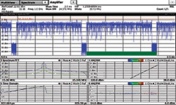
Figure 6 Arbitrary waveform where the signal represents SLSSID = 288 in the FSW-K18 power amplifier measurement option. The AM/AM and AM/PM conversions are shown in the bottom right display.
The signal analyzer measures the output signal of the power amplifier, compares it to the reference waveform and calculates the distortion. Based on the measured distortion and the applied settings, the power amplifier measurement software of the signal and spectrum analyzer calculates a pre-distortion model that is transferred back to the signal generator. The signal generator applies the automatically calculated distortion model to the signal, and the effects are measured in real time on the signal analyzer.
Conclusion
With 3GPP release 12, a first set of features is added to enhance LTE to support the functionality for critical and tactical communications, such as direct mode (direct discovery, direct communication) and group communication. Those features, in particular direct communication in the case of being out-of-coverage, require a new set of synchronization signals that are periodically transmitted by a handset acting as a synchronization source. These signals can provide challenging signal characteristics to a handset power amplifier, since they can have a high PAPR and CM, higher than today’s generic LTE uplink signal. The task of the power amplifier design engineer is to verify and validate that current and future products still fulfill the standard requirements and that lately derived DPD and ET models are still functional.