
A tri-band substrate integrated waveguide (SIW) bandpass filter is based on a suitably defined frequency transformation and well-established prototype synthesis techniques, where coupling coefficients and external quality factors can be calculated analytically. In this realization, an inverter coupled resonator section replaces each capacitance as the basic building block in the lowpass prototype circuit. A practical cross-coupled tri-band SIW filter is designed and fabricated with passbands at 5.85 to 5.9 GHz, 6.05 to 6.15 GHz and 6.25 to 6.35 GHz, respectively. Measured results show good agreement with analysis.
Multi-band bandpass filters (BPF) are key components in modern wireless communication systems. They simplify the system architecture while reducing circuit mass and volume. Tri-band BPFs have been extensively investigated and various design approaches have been reported. Among these techniques, the use of multi-mode resonators to build up tri-band BPFs are the most popular.1-4 A tri-band BPF is designed by Hsu et al.,1 using cascaded stepped impedance resonators (SIR) with controllable second and third harmonics. Composite resonators consisting of split-ring resonators are used as well.2 To further reduce size, the combination of one set of half-wavelength resonators and one set of stub-loaded resonators is used.3,4 The dependence on the resonant frequencies and coupling coefficients of multi-mode resonators, however, complicates tri-band BPF design. Alternatively, synthesis methods for dual-band filters using frequency transformations are used where the analytical and systematic design procedure is attractive.5,6 In addition, SIW has been widely applied to microwave and millimeter wave circuit design due to its high-Q factor and high power handling capability, as well as its low cost and ease of integration.7-8
In this article, a cross-coupled tri-band SIW BPF based on frequency transformation is described. First, the frequency transformation from the actual frequency domain to the normalized frequency domain is derived. Then, the coupling coefficients and the external quality factors of the tri-band BPF topology are calculated. Lastly, a practical cross-coupled tri-band SIW BPF operating at 5.85 to 5.9 GHz, 6.05 to 6.15 GHz and 6.25 to 6.35 GHz with two normalized transmission zeroes at ± j1.8, is designed and fabricated. Measured results show good agreement with simulation.
Figure 1 Frequency transformation from ω-domain to Ω-domain.
SYNTHESIS BY FREQUENCY TRANSFORMATION TECHNIQUE
The ω-domain response of the tri-band BPF that operates at passbands (ωL1, ωH1 ), (ωL2, ωH2 ) and (ωL3, ωH3)is shown in Figure 1. The lowpass prototype operates at the normalized Ω frequency domain and the frequency transformation function from the actual ω-domain to the normalized Ω-domain is:
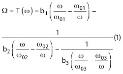
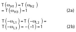
The six unknown coefficients b1, b2, b3, ω01, ω02 and ω03 that define the transformation can be analytically determined by imposing suitable requirements. To determine these parameters, it can be assumed that the lower limits (ωL1, ωL2, ωL3) of the three passbands map to -1 in the normalized Ω domain, while the upper limits (ωH1, ωH2, ωH3) map to 1. Taking into account that the transformation T(ω) in (1) is an odd function, these mapping relationships can be expressed as follows:
Expressing the transformation Equation 1 as the ratio of two polynomials and substituting it into U(ω) = T(ω)-1, yields the following rational function:
 (3)
(3)
where,
The frequencies –ωL1, ωH1, -ωL2, ωH2, -ωL3, ωH3 are the zeroes of U(ω), i.e., they are the roots of the numerator N(ω); so, the unknown parameters n0 ~ n5 can be easily determined by solving a set of linear equations.
Using Equations 4a through 4e, the six parameters that define the transformation T(ω) can be expressed as follows:
Figure 2 Element transformation from Ω-domain to ω-domain.
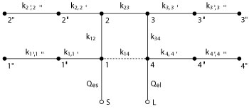
Figure 3 Fourth order cross-coupled tri-band BPF topology. Each black node represents a resonator; the lines represent the couplings.
Applying the above frequency transformation, a normalized unit capacitance in the lowpass prototype can be transformed to an inverter coupled resonator section (see Figure 2).
With the previous analysis and cross-coupled lowpass prototype, a fourth order cross-coupled tri-band BPF is constructed with the topology depicted in Figure 3. Note that the first resonators of the inverter-coupled resonator sections are cross-coupled and the coupling coefficients between these resonators can be expressed in the form of matrix K:
K=M/b1 (6)
where M is the coupling matrix of the cross-coupled lowpass prototype. The coupling coefficients of the resonators inside the inverter coupled resonator section are expressed as:
and the external quality factors at the source and load terminals can be calculated using the following expressions:

where R1 and RN are the source and load impedance of the lowpass prototype, respectively.
Figure 4 Tri-band SIW BPF layout.
Figure 5 Extracted external quality factor and coupling vs. physical parameters.
CROSS-COUPLED TRI-BAND SIW BPF DESIGN
Based on the above synthesis procedure, a new fourth order cross coupled tri-band SIW BPF is designed. The three operating bands are 5.85 to 5.95 GHz, 6.05 to 6.15 GHz and 6.25 to 6.35 GHz, and each band features a 20 dB maximum return loss. A generalized Chebyshev lowpass prototype with two finite transmission zeros at ± j1.8 and 20 dB return loss are first synthesized. Then, the coupling coefficients and the external quality factors are calculated employing Equations 6 through 8 as follows:
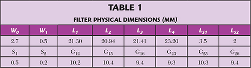
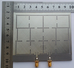
Figure 6 Photograph of the fabricated tri-band SIW BPF.
Finally, the circuit is realized with SIW structures. The relative dielectric constant, thickness and loss tangent of the substrate are 2.65, 1 mm and 0.001, respectively. The diameter of each metal hole is 1.5 mm and the distance between holes is 2.25 mm. The layout is shown in Figure 4. HFSS is used to extract the relationships between the coupling coefficients and corresponding physical dimensions that are shown in Figure 5. By using Figure 5 along with some optimization, the final physical parameters are obtained (see Table 1).
MEASURED RESULTS
Figure 6 is a photograph of the fabricated filter. Figure 7 compares the simulated frequency response using HFSS with the measured response using Keysight’s 8719ES network analyzer. The fabricated BPF operates from 5.85 to 5.95 GHz, 6.05 to 6.15 GHz and 6.25 to 6.35 GHz centered at 5.89, 6.09 and 6.3 GHz, respectively. Measured results show good agreement with simulation. The simulated insertion loss is about 1.5 dB at the three center frequencies, while measured losses are 2.27, 2.11 and 2.31 dB. Differences are attributed to dielectric losses and process tolerances.
CONCLUSION
A new cross-coupled triple-band SIW BPF is analyzed based on the frequency transformation technique. The relationship between parameters defining the transformation and the passband limit frequencies of the three passbands is derived and expressions for coupling coefficients and external quality factors are given. The theoretical frequency response of the filter meets its prescribed specifications and is verified through measurement.
References
Figure 7 Comparison of simulated and measured results.
- C.I.G. Hsu, C.H. Lee and Y.H. Hsieh, “Tri-Band Bandpass Filter With Sharp Passband Skirts Designed Using Tri-Section SIRs,” IEEE Microwave and Wireless Components Letters, Vol. 18, No. 1, January 2008, pp. 19–21.
- R.H. Geschke, B. Jokanovic and P. Meyer, “Filter Parameter Extraction for Triple-Band Composite Split-Ring Resonators and Filters,” IEEE Transactions on Microwave Theory and Techniques, Vol. 59, No. 6, June 2011, pp. 1500–1508.
- X.Y. Zhang, Q. Xue and B.J. Hu, “Planar Tri-Band Bandpass Filter With Compact Size,” IEEE Microwave and Wireless Components Letters, Vol. 20, No. 5, May 2010, pp. 262–264.
- Q.X. Chu, X.H. Wu and F.C. Chen, “Novel Compact Tri-Band Bandpass Filter With Controllable Bandwidths,” IEEE Microwave and Wireless Components Letters, Vol. 21, No. 12, December 2011, pp. 655–657.
- G. Macchiarella and S. Tamiazzo, “Design Techniques for Dual-Passband Filters,” IEEE Transactions on Microwave Theory and Techniques, Vol. 53, No. 11, November 2005, pp. 3265–3271.
- J. Lee and K. Sarabandi, “A Synthesis Method for Dual-Passband Microwave Filters,” IEEE Transactions on Microwave Theory and Techniques, Vol. 55, No. 6, June 2007, pp. 1163–1170.
- Q.L. Zhang, W.Y. Yin, S. He and L.S. Wu, “Compact Substrate Integrated Waveguide (SIW) Bandpass Filter With Complementary Split-Ring Resonators (CSRR),” IEEE Microwave and Wireless Components Letters, Vol. 20, No. 8, August 2010, pp. 426–428.
- Y. Dong and T. Itoh, “Substrate Integrated Waveguide Loaded by Complementary Split-Ring Resonators for Miniaturized Diplexer Design,” IEEE Microwave and Wireless Components Letters, Vol. 21, No. 1, January 2011, pp. 10–12.