
With shrinking defense budgets and smaller military forces relying on greater technological capabilities, the push is stronger than ever to do more with less while at the same time meeting unprecedented performance and reliability requirements. In response to these pressures, test tools must provide greater ease of use, lower test costs and perhaps most importantly, cutting edge performance.
The aerospace and defense (A&D) environment can be broken up in several ways. When discussing test and measurement equipment it is best to divide it into separate functional areas as shown in Figure 1. Common technologies include, but aren’t limited to, array antennas, multi-function systems, mixed-signal processing and mmWave.
ADVANCED CAPABILITIES NEEDED FROM TEST EQUIPMENT
The development of new and advanced EW, radar and communications systems drives requirements for performance and usability of signal simulation and analysis equipment. Test systems must employ wider bandwidth signals and move acquired or stored RF signal data from one instrument or storage element to another in a real time environment. Data transfer rates on the order of 10 GB/s (equivalent to about 2 GHz RF bandwidth) are required. High speed (to real time) reduction and analysis of massive data streams within the instrument is a common need. This must be accomplished in the FPGA, DSP or GPU; the instrument controller can no longer be relied upon. Operations include digital up- and down-conversion, simultaneous high resolution time and frequency display and real time signal generation from acquired raw data or data generated algorithmically for playback.
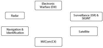
Figure 1 A&D applications for test and measurement.
Many technologies including radar, EW and SIGINT are moving to multiple distributed apertures for higher performance and more capability. Multi-aperture, multi-function systems require multiple, coherent RF channels for signal generation and analysis.
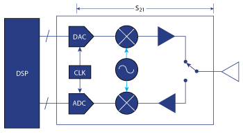
Figure 2 T/R module concept for digital array radar.
TESTING ARRAY ANTENNAS AND TRANSMIT/RECEIVE MODULES (TRM)
In radar and EW systems the use of active electronically scanned array (AESA) antennas has become nearly ubiquitous for their many advantages. They enable operation in multiple modes to engage several targets simultaneously and take advantage of powerful signal processing capabilities for threat discrimination. Because the beam can be formed and steered electronically, no gimbal is required, permitting agile beam repositioning at extremely high rates.
For satellite applications, rapid electronic repositioning of the antenna beam or the use of multiple beams permits a single AESA to communicate with multiple spatially distributed ground stations. Distributed TRMs provide an architecture tolerant to failure, providing high reliability in a harsh environment. Also, the antenna can be located on the surface of a spacecraft to avoid physical deployment.
A concept gaining favor for reducing AESA characterization time is using a wider bandwidth signal than is typically available with a traditional network analyzer. With a wideband signal, a group of frequency states is tested at one time, and the wide bandwidth stimulus more closely matches device or system operating conditions.
Digital broadband signal processing is moving closer to the antenna, creating a digital array radar (DAR), where the only connection to the TRM is a digital bus (see Figure 2). It poses a new and unique problem when one side of a network is comprised of several lanes of digital data representing what began as an analog signal on the other side. A new methodology is needed to measure network response parameters. Parameters like true time delay might be extracted from the DSP rather than from analog measurements of phase and amplitude. Digital interconnects and serializer/deserializer links add their own distortion and latency that must be characterized.
NEED FOR SOFTWARE DEFINED TEST SYSTEMS
A&D system architectures are becoming more integrated (see Figure 3), sharing physical resources such as antennas and processors to reduce size, weight and power (SWaP) as well as sharing information to make better and more timely decisions, such as how to configure in a given environment or react to a specific threat. This, in turn, drives changes in the way these systems are evaluated. Like the systems they assess, test solutions must use common hardware elements, be software and firmware definable and rapidly reconfigured when required.
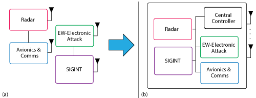
Figure 3 Systems that have historically operated independently (a) are more integrated (b).
MIXED SIGNAL TESTING REQUIRES COMPARATIVE MEASUREMENT
In modern satellite, radar and EW architectures, formats change as the signal passes through the transmitter and receiver. The signal is often represented on time sampled dual I/Q signal busses, which further complicates testing. Diagnosing digital issues requires different test interfaces to different hardware and the probing of I/Q busses with many test connections. Probing is often complicated when using FPGAs, as many of the desired test points may not be accessible outside of the chip.
As illustrated in Figure 4, cross format analysis is often needed for troubleshooting. For A&D systems, it is frequently necessary to compare an analog signal with the originating digital signal, requiring a cross-domain analysis capability. Comparative analysis can extend well beyond baseband I/Q measurements, continuing through IF and RF frequencies to Ka-Band and higher into the mmWave region.
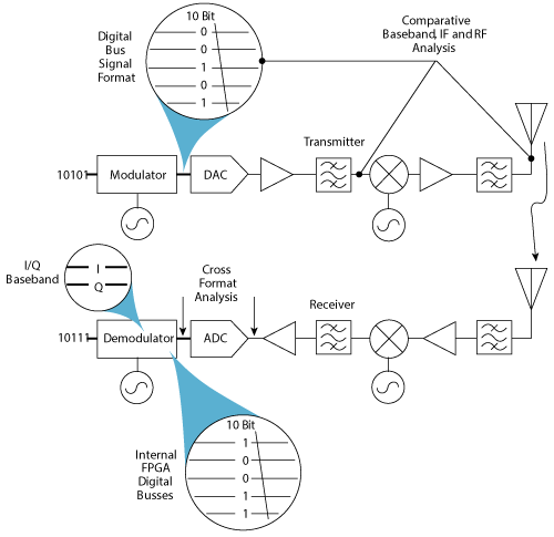
Figure 4 Test challenges with mixed signal implementation.
Vector signal analysis (VSA) software using the same measurement algorithms that can be used with logic analyzers, digital oscilloscopes, and RF signal analyzers is needed to ensure proper comparison of results. This enables the performance of a mixed-signal digital/RF transmitter chain to be probed at various stages, providing the system engineer with insight into which sections of the design are causing issues or contributing the most to transmitter output error vector magnitude (EVM). This can be valuable both to debug and budget system-level transmitter performance.
If FPGAs are used, an FPGA dynamic probe can probe at various stages of the FPGA design using the VSA software with a logic analyzer. The same VSA software can then be used with a digital oscilloscope or RF signal analyzer at points further along the transmit and receive chain.
NEW APPLICATIONS IN mmWAVE
The smaller wavelengths at mmWave frequencies (30 to 300 GHz) enable antenna dimensions to be small compared with microwave antennas, so transmitter and receiver systems can be very compact. Smaller wavelengths also enable higher resolution, particularly for synthetic aperture radar (SAR). With a smaller user base, mmWave bands tend to be much less cluttered than the VHF, UHF and microwave frequency bands. Additionally, large modulation bandwidths can be realized with the current abundance of available spectrum.
In contrast to the advantages offered by mmWave systems, there are also a number of challenges and difficulties. Millimeter wave signals have a poor ability to penetrate materials and are easily blocked. Losses through most propagation mediums, such as the atmosphere, or through transmission lines like coaxial cable or waveguide are very high. Because the physical dimensions decrease, the associated hardware becomes smaller and more fragile. That also means that it is harder to manufacture and machine to the tolerances needed for adequate performance. The combination of these factors, along with the lower volume of mmWave products manufactured, keeps costs high. These challenges are faced by the test equipment industry, as well.
CONCLUSION
Test equipment must adapt and improve to support the applications enabled by advancing A&D system technologies. Flexible, reconfigurable software-defined mixed-signal instrumentation provides a method for controlling test costs through hardware reuse and reduced time to first measurement.