
A compact microstrip lowpass filter (LPF) employing modified circular resonant patches and folded lines has a sharp rolloff, an ultra-wide stopband from 4.5 to 32 GHz with 26.2 dB attenuation and insertion loss of less than 0.12 dB.
Microstrip lowpass filters (LPF) are important for the suppression of undesired signals in microwave communication systems. A sharp transition band, a wide stopband and low passband insertion loss are key performance characteristics. Conventional LPF design methods are not normally used due to inherent deficiencies such as slow roll-off, poor frequency response in the passband and a narrow stopband.1
Ma and Yeo describe an ultra-wide stopband LPF using transformed radial stubs,2 however its passband insertion loss and return loss are poor and the structure is complex. A compact LPF with a wide stopband using a stepped-impedance compact microstrip resonator cell (SICMRC) has been proposed by Hayati and Abbasi.3 It has adequate insertion loss and return loss in the passband but exhibits a gradual roll-off in the transition band. The use of a G-shaped defected microstrip structureprovides a sharp roll-off with negligible radiation loss, but the return loss and passband insertion loss are inadequate.4 The structure is large in size as well. Another approach using a front-coupled tapered compact microstrip resonator cell (CMRC), has been employed in an attempt to achieve compact size; however, the filter has a gradual roll-off and a narrow stopband.5
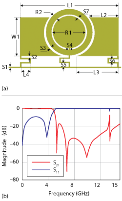
Figure 1 Resonator layout (a) and frequency response (b).
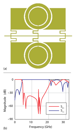
Figure 2 Modified resonator layout (a) and frequency response (b).
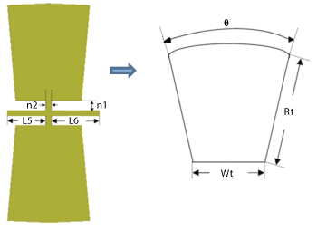
Figure 3 Suppressing cell layout.
In recent years, defected ground structures (DGS) have been used in a variety of different ways for LPF applications.6,8,9,10 Although they have improved stopbands, the etched ground of the DGS causes radiation problems.Passband insertion loss is generally poor, and total size is large. Al-Omair et al., introduce designs of compact LPFs and bandpass filters based on a DGS using two complementary split ring resonators (CSRR) that are etched in the ground plane.9 The return loss and the insertion loss in the passband are inadequate, however, the filter is large in sizewith a narrow stopband. A patterned ground and its equivalent lumped circuit model are analyzed in depth by Shao and Li,11 however, the LPF is also large size with a narrow stopband. Chen et al.,12 describe a compact wide stop-band koch-shaped electromagnetic bandgap microstrip LPF. By forming the low impedance segments with fractal shapes,13 the passband performance of a stepped-impedance LPF can be modified, but this structure has gradual roll-off in the transition band.
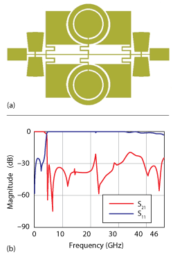
Figure 4 Two-cell LPF layout (a) and frequency response (b).
This article introduces a compact microstrip LPF with an ultra-wide stopband, sharp roll-off, high return loss and low passband insertion loss. This is achieved with modified circular resonant patches and folded lines.
LPF DESIGN
The LPF design starts with a resonator that achieves a sharp roll-off. Its performance is improved by mirroring, to form a modified resonator. Suppressing cells are added to eliminate harmonics, resulting in a two-cell filter. A four-cell filter uses the two-cell filter in a cascaded form.
Resonator Design. The layout and dimensions of the resonator are shown in Figure 1a. Using high-impedance folded transmission lines instead of straight ones not only reduces the circuit size but also improves the transition band. The frequency response of the resonator is shown in Figure 1b. It has a wide stopband with three transmission zeros at approximately 5.32, 6.82 and 9.87 GHz with attenuation levels of 51.14, 70.91 and 54.79 dB, respectively. The dimensions of the resonator are optimized using Keysight’s Advanced Design System (ADS) electromagnetic simulator. After optimization, the dimensions of the proposed resonator are L1 = 7 mm, L2 = 2.1 mm, L3 = 3 mm, L4 = 0.68 mm, W1 = 2.75 mm, R1 = 1.15 mm, R2 = 0.4 mm, S1 = S2 = S4 = S7 = 0.1 mm, S3 = 0.14 mm, S5 = 0.23 mm and S6 = 0.2 mm.
Mirroring. The modified resonator is shown in Figure 2a. It is apparent from Figures 1b and 2b, that the location of the first transmission zero is reduced from 5.32 to 5 GHz, resulting in a sharper roll-off; insertion loss and return loss in the passband are improved and the width of the stopband is extended to 14.6 GHz.
Suppressing Cell Design and Integration.The layout of the suppressing cell is shown in Figure 3. Its dimensions are L5 = 0.65 mm, L6 = 0.8 mm, n1 = 0.1 mm, n2 = 0.15 mm, Rt = 1.6 mm, Wt = 1.1 mm and u= 10 degrees. To extend the width of the stopband and increase attenuation levels, four high-impedance lines loaded with radial stubs are added to the modified resonator. The layout and frequency response of a two-cell LPF are shown in Figures 4a and 4b, respectively. As shown Figure 4b, the two-cell LPF has a stopband rejection better than 20 dB from 4.65 to 46 GHz, insertion loss of less than 0.06 dB and return loss greater than 25 dB in the passband.
Four-cell filter design.The layout and frequency response of the four-cell filter are shown in Figures 5a and 5b, respectively. As shown in Figure 5a, the distance between the modified resonators in cascaded form is S8 = 0.15 mm and dimensions of the matching ports are Wf = 1 mm and Lf = 1.6 mm. In Figure 5b, the four-cell LPF has a stopband rejection better than 26 dB from 4.5 to 32 GHz, with an insertion loss of less than 0.12 dB and return loss of more than 16.4 dB in the passband. The frequency response is sharp with the transition band equal to 0.24 GHz from 4.26 to 4.5 GHz and corresponding attenuation levels of -3 and -20 dB, respectively.
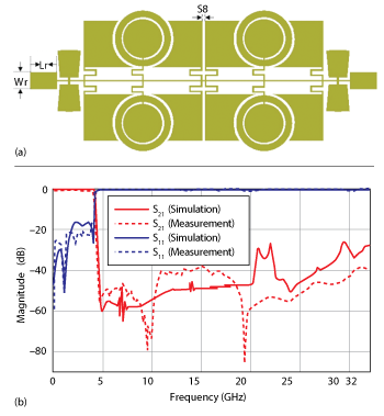
Figure 5 Four-cell LPF layout (a) and frequency response (b).
SIMULATED AND MEASURED RESULTS
A photograph of the fabricated LPF is shown in Figure 6. The four-cell LPF is fabricated on an RT/Duroid 5880 substrate with relative dielectric constant εr = 2.2, thickness h = 0.508 mm and loss tangent tan δ = 0.0009. The LPF is simulated using the method of moments in ADS, and the KeysightN5230A network analyzeris used for measurement.
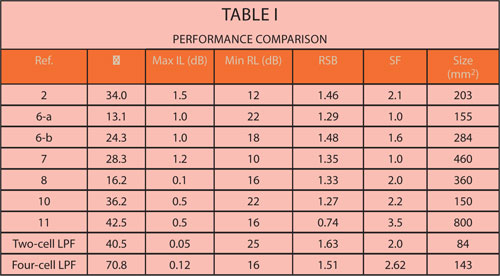
LPF performance is compared with other works in Table 1, where the rolloff rate (ξ), relative stopband bandwidth (RSB), and suppression factor (SF) are defined as:

where αmax is the -20 dB attenuation point, αmin is the 3 dB attenuation point, fs is the 20 dB stopband frequency and fc is the 3 dB cut-off frequency.


Conclusion
This compact LPF exhibits a sharp roll-off, an ultra-wide stopband, compact size, high return loss and low insertion loss in the passband – features needed for modern microwave communication systems.Good agreement between simulated and measured results is demonstrated.
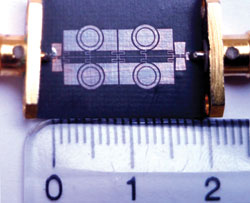
Figure 6 Photograph of the four-cell LPF.
References
- J. S. Hong and M. J. Lancaster, “Microstrip Filters for RF/Microwave Applications,” Wiley, New York, 2001.
- K. Ma and K. S. Yeo, “New Ultra-Wide Stopband Low-Pass Filter Using Transformed Radial Stubs,” IEEE Transactions on Microwave Theory and Techniques, Vol. 59, No. 3, March 2011, pp. 604–611.
- M. Hayati and H. Abbasi, “Compact Microstrip Stepped-Impedance Lowpass Filter with Wide Stopband Using SICMRC,” Institute of Electronics, Information and Communication Engineers Electronics Express, Vol. 9, No. 22, November 2012, pp. 1742–1747.
- H. Cao, W. Guan, S. He and L. Yang, “Compact Lowpass Filter With High Selectivity Using G-Shaped Defected Microstrip Structure,” Progress In Electromagnetics Research Letters, Vol. 33, 2012, pp. 55–62.
- M. Hayati and A. Lotfi, “Compact Lowpass Filter with High and Wide Rejection in Stopband Using Front Coupled Tapered CMRC,” Electronics Letters, Vol. 46, No. 12, June 2010, pp. 846–848.
- S. Xu, K. Ma, F. Meng and K. S. Yeo, “DGS Embedded Transformed Radial Stub for Ultra-Wide Stopband Lowpass Filter,” Electronics Letters, Vol. 48, No. 23, November 2012, pp. 1473–1475.
- F. Wei, L. Chen, X. W. Shi, Q.L. Huang and X.H. Wang, “Compact Lowpass Filter With Wide Stop-Band Using Coupled-Line Hairpin Unit,” Electronics Letters, Vol. 46, No. 1, January 2010, pp. 88–90.
- M. Challal, A. Boutejdar, M. Dehmas, A. Azrar and A. Omar, “Compact Microstrip Low-Pass Filter Design With Ultra-Wide Reject Band Using a Novel Quarter-Circle DGS Shape,” Applied Computational Electronics Society Journal, Vol. 27, No. 10, October 2012, pp. 808–815.
- G. E. Al-Omair, S. F. Mahmoud and A. S. Al-Zayed, “Lowpass and Bandpass Filter Designs Based on DGS with Complementary Split Ring Resonators,” Applied Computational Electronics Society Journal, Vol. 26, No. 11, November 2011, pp. 907–914.
- A. Faraghi, M. N. Azarmanesh and M. Ojaroudi, “Small Microstrip Low-Pass Filter by Using Novel Defected Ground Structure for UWB Applications,” Applied Computational Electronics Society Journal, Vol. 28, No. 4, April 2013, p. 341.
- W. Shao and J. L. Li, “Accurate Modeling of a Patterned Ground and Its Application to Microwave Filters,” Applied Computational Electronics Society Journal, Vol. 27, No. 7, July 2012, pp. 596–602.
- W. L. Chen, G. M. Wang and Y. N. Qi, “A Compact Wide Stop-band Koch-Shaped Electromagnetic Bandgap Microstrip Low Pass Filter,” Microwave Journal, Vol. 50, No. 10, October 2007, p.160.
- W. L. Chen and G. M. Wang, “Enhancement of Microstrip Stepped-Impedance Low-Pass Filters Using Fractal-Shapes,” Microwave Journal, Vol. 52, No. 7, July 2009, p. 64.
Mohsen Hayati received his B.E. degree in electronics and communication engineering from Nagarjuna University, India, in 1985 and his M.E. and Ph.D. degrees in electronics engineering from Delhi University, Delhi, India, in 1987 and 1992, respectively. He joined the electrical engineering department at Razi University, Kermanshah, Iran as an assistant professor in 1993. He is currently an associate professor in the same department. Hayati’s research interests include microstrip filter design for communication systems, application of computational intelligence, artificial neural networks, fuzzy systems, neuro-fuzzy systems and electronics circuit synthesis, modeling and simulation.
Parisa Karami Moghadam received her B.Sc. degree in electrical engineering from Razi University, Kermanshah, Iran and her M.Sc. degree in electrical engineering from Kermanshah Science and Research Branch, Islamic Azad University, Kermanshah, Iran. Her research interests include the analysis and design of microstrip filters and antennas.