
The Current State of the Art in Coplanar MMICs
Thomas Sporkmann
Institut für Mobil- and Satellitenfunktechnik
Kamp-Lintfort, Germany
In part one of this article (published in the July issue of Microwave Journal), the evolution of coplanar line techniques over the last 30 years was presented and alternatives for designing coplanar circuits were discussed. In addition, an efficient three-dimensional finite-difference method for generating a comprehensive library of coplanar elements within HP EEsof’s Libra™ series IV electromagnetic simulator was explained. This library is the most complete and advanced tool for designing coplanar MMICs at this time. The integration into series IV and the verification of this library as well as various applications designed using the library are presented in this article.
Currently, 16 standard elements and three types of air bridges are available in the COPLAN for Libra software. Appendix A lists the utilized elements, their physical geometries and applied electrical equivalent circuits. The complete three-
dimensional simulation and foundry-oriented layout for each structure are implemented in the series IV software. All of these elements have been verified extensively to approximately 70 GHz by various companies. (Some of the verification data are discussed in this article.)
 Utilizing the COPLAN for Libra library, each dimension and other physical parameters can be varied within the software. Thus, circuit optimization utilizing field simulation is accomplished easily.
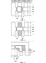
Three types of air bridges are available for different applications and technologies. All of the bridges can be applied to the discontinuities automatically and then included in the simulation and layout. Figure 1 shows the three air bridge types and the dimensions that can be modified. Any modification is automatically considered in the simulation and related layouts. Two different metal layers are utilized for the air bridges. In addition, it is also possible to place dielectric material between the two metal layers, a capability that is quite important for certain foundries.
Integration of the COPLAN for Libra Library into Series IV
The COPLAN for Libra library consists of coplanar waveguide models and special data items. Each model represents a specific coplanar structure such as a T-junction or bend. Several data items have been introduced to reduce the number of input parameters for these models. These data items have functions that are similar to the well-known data items such as MSUB of the microstrip library or the general UNIT data item. Many of the necessary input parameters are common for many of the elements in a given design. As a result, these parameters are stored in dedicated data items. For example, a 50 W line is defined by the line width w and slot s. Normally, all 50 W lines in a design have the same w and s values. These data are stored in the C_LINTYP item and can be referenced by all modules without entering the information repeatedly. The same is true for the bridge configurations and grids.
In addition, the library supports process-related layout generation, which means that all necessary information (for example, oversizes and layer configurations) is stored in two additional data items. Technological data such as layer material constants (dielectric constants, loss factors and resistivity) and layer height are maintained in the C_TECH data item. A second data item, C_LAYER, is intended for layer data such as layer number and oversize.
A standard foundry setup is available that allows the user to adjust several process-specific parameters. However, additional adaptations to other foundries may be necessary and are available as a special service. It is important to note that COPLAN for Libra supports the use of several foundries and processes simultaneously. Using the quasistatic finite-difference approach, an equivalent circuit is computed during a frequency-independent pre-analysis. The number of iterations, residual error and model name are displayed inside the standard Libra status window. The input parameters and results are stored in a database file. During simulator startup, this file is loaded into memory and then works like a cache. Based on these previous results, a frequency-dependent analysis is started and the S parameters of all coplanar structures are calculated.
A smart cache memory management procedure is implemented to speed up the statistical analysis and optimization process. The calculated parameters of coplanar elements are stored in this cache during the first analysis run and are updated if the element data are changed.
COPLAN for Libra is supplied with the data items listed in Table 1 . The calculated parameters are also stored in binary look-up tables. These files contain the equivalent circuit parameters of all coplanar elements and the characteristic line parameters of coplanar waveguides.
|
Table I | |
|
C_SUB |
Substrate definition for coplanar structures |
|
C_GRID |
Definition of grid and shielding sizes for finite differences approach |
|
C_LINTYP |
Definition of cross-sectional dimensional of coplanar line |
|
C_AIRTYP |
Definition of air bridge parameters |
|
C_PROCES |
Foundry selection for layout generation and process-related simulation |
|
C_TECH |
Definition of technological data for selected foundry |
|
C_LAYER |
Definition of layer data for selected foundry |
 The library can be accessed by selecting the Coplanar Elements palette in the schematic and layout windows, as shown in Figure 2 . In the case of default definitions, a palette is located in the defaults window as well.
 The complete schematic, simulation and layout library is thus integrated seamlessly into series IV and may be utilized as simple resistors or other lumped elements. This approach offers linear and nonlinear simulations as well as circuit optimization. Figure 3 shows a filter circuit schematic that was designed utilizing COPLAN; Figure 4 shows the corresponding layout that is
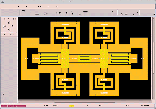 extracted automatically from the schematic. However, it is also possible for designers to start from layouts or modify dimensions within the layout presentation.
Verification of the COPLAN for Libra Library
Verification of COPLAN for Libra began in 1992 with the launch of the three-year ESPRIT-CLASSIC project during which many passive coplanar structures were fabricated and measured up to 67 GHz. The measurements then were compared to simulations utilizing COPLAN for Libra. These verifications demonstrated good results for all elements depicted. However, several companies (such as Alcatel, Dassault, Hughes and Ricoh) and research labs (such as IMEC and FhG-IMS) also produced test structures and verified measurements against simulations. Currently, not a single company has reported poor software accuracy. Since the library was also verified by extensive circuit designs, selected results of this work will be presented as well.
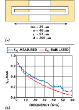 The following examples are typical of verification procedures conducted at IMST. All of the displayed structures were realized on GaAs with a conventional MMIC technology. Extra layers or special design rules were not required. Loss simulations and characteristic line behavior were investigated first. Various structures for impedances between 30 and 80 W were realized and evaluated. Figure 5 show results from a 25-mm-long line on GaAs.
  Return and insertion loss were simulated in almost perfect agreement for both magnitude and phase. Measurements and simulated data for a double step structure are shown in Figure 6 . A more complex structure comprising 24 air bridges, 12 bends and the associated connecting lines is shown in Figure 7 . This structure generates resonances at low frequencies. A strong resonance can be detected at 30 GHz. All resonances are simulated perfectly in frequency, magnitude and phase.
 Various tee and cross structures, which are two-port configurations, also were evaluated. The remaining parts typically connect to transmission lines, which terminate into opens or
  shorts. Thus, each resonance must occur as a function of n x l /4 (n = 1, 2...) of these stubs.
Figure 8 shows data from tee structure measurements and corresponding simulations. Only a small deviation between the two data sets at 50 GHz can be found. This small discrepancy is due to increasing dispersion at high frequencies. The dispersion was not considered in the simulation for the displayed examples. However, it can be seen that even the phase behavior can be predicted with good accuracy.
 Lumped elements such as rectangular inductors, interdigital capacitors, thin-film resistors and metal-insulator-metal (MIM) capacitors also were evaluated during the ESPRIT-CLASSIC project. Data from a 3.5-turn inductor are shown in Figure 9 . In this case, the simulation is very good up to 30 GHz and
 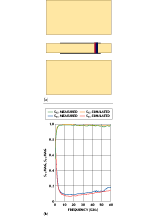 degrades only marginally at higher frequencies. As a last example, data from an MIM capacitor are shown in Figure 10 . As in other cases, the simulated data are in good agreement with the measured data.
Applications Realized by Utilizing COPLAN
COPLAN users can be found in almost every country. Thus, current applications exist in almost every modern system. Unfortunately, most of these applications are not accessible to the public and will only find their way into publications after some time. However, MMIC and MIC design activities at IMST are ongoing and some results of this work are presented here.
Applications at IMST include 900 MHz highly linear base station components over a 2.4 GHz low power radio link for transponders, 5.8 GHz oscillators, various-frequency up- and downconverters, 24 GHz radar sensors, TX and RX modules for satellite links at 20 and 30 GHz, components for 38 GHz point-to-point systems and 77 GHz components for today’s modern adaptive cruise control (ACC) systems. All circuits for these applications were realized in coplanar techniques utilizing high electron mobility transistor (HEMT) or MESFET technologies; some of the circuits designed with COPLAN are presented in this article.
 The 29 GHz oscillator, shown in Figure 11 , was realized using a conventional 0.5 mm MESFET process and features 5 dBm output power. The oscillator is used in satellite-based communication systems and is a two-stage design with active loads and lumped inductors for biasing. The resonator is realized on chip by a combination of inductors and a voltage-dependent capacitor (diode). The chip size is 1.24 mm2 .
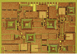
The 38 GHz oscillator, shown in Figure 12 , is based on a 0.25 mm HEMT  process and was designed as part of an ESPRIT project together with the Daimler-Benz GaAs foundry. This 1.23 x 0.75 mm single-stage oscillator utilizes an active load and on-chip resonator.
The third example, shown in Figure 13 , features a 5 GHz oscillator for a distance measurement system. In this case, a three-stage design was required to reduce oscillator load pulling. The output power is 10 dBm at the main port and 0 dBm at the phase-locked loop port. The Daimler-Benz 0.5 mm MESFET  process and active biasing combined with inductors and capacitors are utilized for this chip. This oscillator can be tuned over more than a 4 GHz bandwidth and is available with on-chip and external varactor elements.
All presented oscillators were fully simulated by utilizing the series IV software in combination with COPLAN. The output power and oscillation frequency could be predicted accurately prior to fabrication utilizing a nonlinear model for the active devices. 
The fourth example in this series is a broadband SPDT switch with a TTL-compatible driver, as shown in Figure 14 . The switch’s input and output are matched to 50 W and the operating frequency band ranges from approximately 1 to 12 GHz. The switch’s return loss is better than 10 dB over the entire frequency band and isolation is better than 25 dB (> 40 dB at 2 GHz) with approximately 1.5 dB insertion loss. This 0.2 mm2 circuit was realized utilizing a 0.5 mm MESFET process and using the COPLAN software for simulation and prediction.
Various MMICs were designed at IMST during the ESPRIT-CLASSIC  project. The high frequency applications for these circuits were ACC systems and the Mobile Broadband System, which are well suited for coplanar technology. One of the components designed at IMST during this project, an upconverter that operates from 6 to 60 GHz, is shown in Figure 15 . The upconverter achieved a conversion gain of 11 dB with an LO frequency of 56.8 GHz and a chip size of approximately 2.1 mm2 . This active two-stage mixer (with adder stage at the input) was realized utilizing the Thomson and Daimler-Benz 0.15 mm HEMT process. Both the LO and input RF signals are applied at the gate of the mixing device. All ports are matched to 50 W at the corresponding frequencies. Matching was achieved at the RF port (5.2 to 7.2 GHz) by a combination of lumped inductors and MIM capacitors. This circuit was fully simulated within series IV utilizing COPLAN and a nonlinear model for the HEMTs.
 A 2.4 GHz amplifier with three output ports is shown in Figure 16 . The circuit contains six integrated active devices featuring additional active loads, rectangular inductors and MIM capacitors for matching purposes. This amplifier has a chip size of 5.23 mm2 and offers one 0 dBm and two 10 dBm output ports. The input is matched to the corresponding oscillator with a low impedance. The devices in this circuit were selected for low power applications. Thus, biasing is at low currents with approximately 10 dB gain per stage. A conventional 0.5 mm MESFET process was utilized for this circuit.
A complete I/Q demodulator (balanced mixer) for 2.4 GHz to baseband (fIF = 0 Hz to 100 MHz) is 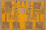 shown in Figure 17 . This chip requires 2.4 mm2 and features on-chip RF and LO matching and LO rejection at the IF port. Measured and simulated conversion loss is approximately 2 dB at 7 dBm input power at the LO port. A conventional 0.5 mm MESFET technology was utilized for processing and the simulation was conducted with COPLAN as well. External couplers are required for dividing/combining the signals at the input and output of the circuit.
Conclusion
This article introduced the COPLAN software library. Integration into Libra series IV software, a comprehensive verification procedure and various applications designed utilizing COPLAN have been discussed as well. The displayed circuits were realized and the measured data compare well with simulation. Historically, coplanar circuit designs have been successfully realized from 1 to 100 GHz. Examples of these designs were presented, indicating there currently is no valid case against utilizing coplanar circuit design techniques. Coplanar circuits can be interfaced with microstrip environments, making co-integration of microstrip and coplanar MMICs possible. Even high power applications utilizing coplanar circuit techniques and flip-chip mounting have been demonstrated successfully.
References
1. C.P. Wen, "Coplanar Waveguide: A Surface Strip Transmission Line Suitable for Nonreciprocal Gyromagnetic Device Application," IEEE-MTT, Vol. 17, December 1969, pp. 1087–1090.
2. P. Wen, "Coplanar Waveguide Directional Couplers," IEEE-MTT, Vol. 18, June 1970, pp. 318–322.
3. V. Fouad-Hanna and D. Thebault, "Theoretical and Experimental Investigation of Coplanar Directional Couplers with Finite Boundary," Proceedings of the Seventh MICROCOLL, September 1982, pp. 588–592.
4. M. Riaziat, I. Zubeck, S. Bandy and G. Zdasiuk, "Coplanar Waveguides Used in 2 to 18 GHz Distributed Amplifiers, 1986 IEEE MTT-S Digest, June 1986.
5. M. Riaziat, I.J. Feng, R. Majidi-Ahy and B.A. Auld, "Single-mode Operation of Coplanar Waveguides," Electronic Letters, Vol. 23, No. 24, November 1987.
6. G. Ghione and C.U. Naldi, "Coplanar Waveguides for MMIC Applications: Effect of Upper Shielding, Conductor Backing, Finite-extent Ground Planes and Line-to-line Coupling," IEEE-MTT, Vol. 35, March 1987, pp. 260–267.
7. T. Tokumitsu et al., "Active Isolator, Combiner, Divider and Magic-T as Miniaturized Function Blocks," 1988 IEEE GaAs Symposium Digest, March 1988, pp. 273–277.
8. N.H.L. Koster, S. Kosslowski, R. Bertenburg, S. Heinen and I. Wolff, "Investigation on Air Bridges Used for MMICs in CPW Technique," 19th EuMC Proceedings, 1989, pp. 666–671.
9. M. Naghed and I. Wolff, "Equivalent Capacitances of Coplanar Waveguide Discontinuities and Interdigitated Capacitors Using a Three-dimensional Finite-difference Method," IEEE MTT, Vol. 38, No. 12, 1990, pp. 1808–1815.
10. M. Naghed and I. Wolff, "A Three-dimensional Finite-difference Calculation of Equivalent Capacitances of Coplanar Waveguide Discontinuities," 1990 IEEE MTT-S Digest, 1990, pp. 1143–1145.
11. M. Naghed, M. Rittweger and I. Wolff, "A New Method for the Calculation of the Equivalent Inductances of Coplanar Waveguide Discontinuities," 1991 IEEE MTT-S Digest, pp. 747–750.
12. P. Pogatzki, R. Kulke, T. Sporkmann, D. Köther, R. Tempel and I. Wolff, "A Comprehensive Evaluation of Quasi-static 3D-FD Calculations for More Than 14 CPW Structures — Lines, Discontinuities and Lumped Elements," 1994 IEEE MTT-S Digest, Vol. 2, May 1994, pp. 1289–1292.
13. R. Kulke, T. Sporkmann, D. Köther, I. Wolff and P. Pogatzki, "Coplanar Elements Support Circuit Design to 67 GHz," Microwaves & RF, December 1994, pp. 103–116, January 1995, pp. 89–95 and February 1995, pp. 112–117.
14. P. Cameron, W. Pan, C. Hanz and R. Nicklaus, "A Flip-chip High Efficiency X-band HPA," IEEE MTT-S Digest, June 1997, pp. 889–892.
15. L. Verweyen, A. Bangert, H. Massler, T. Fink, M. Neumann, R. Osorio, T. Krems, T. Jakobus, W.H. Haydl and M. Schlechtweg, "Compact Integrated Coplanar T/R Modules for Automotive Applications," 1997 IEEE MTT-S Digest, June 1997, pp. 243–246.
16. R. Tempel, W. Lütke, J. Hermann and I. Wolff, "MMICs for Sensor Applications," MMWMC Symposium Digest, June 1996, pp. 209–212.