
Traditional RF/microwave test and measurement (T&M) instruments are dedicated “boxes” built with application specific and general purpose silicon, firmware and embedded software. In contrast, software defined synthetic instruments (SDSI) “synthesize” multiple instruments – spectrum analyzers, digital storage oscilloscopes, RF receivers, signal generators – with digital signal processing (DSP) software and firmware on commercial embedded multicore processors and field programmable gate arrays (FPGA). SDSIs offer advantages over a suite of traditional instruments, dramatically reducing test system life cycle costs. Addressing equipment obsolescence and the portability of test programs are two of their most important benefits, especially to organizations with large fleets of RF/microwave test systems or performing production tests. SDSIs provide a watershed infrastructure for developing test systems that remain stable throughout the test life cycle.
Numerous standards and tools, at several levels of abstraction, are used to develop test programs, more formally known as test program sets (TPS). Interchangeable virtual instrument drivers (IVI) and instrument command sets, such as the standard commands for programmable instruments (SCPI), are at the lowest level. At the next higher level are test development languages, including automated test markup language (ATML), abbreviated test language for all systems (ATLAS) and standard programming languages such as C or C++. At the highest level of abstraction are test executive suites, such as National Instrument’s TestStand, Keysight’s Test Exec SL and Marvin Test’s ATEASY. All of these test executive suites provide a TPS development environment that accommodates multiple instruments and devices under test (DUT).
However, even with all of these tools, obsolescence and TPS portability represent huge challenges to the industry because of the intrinsic hardware dependencies when using separate instruments. A TPS written for a fixed function instrument will likely require significant modification if the hardware changes. If the test executive changes, significant portions of the TPS must be refactored or recreated. A study conducted by the U.S. Army at the Tobyhanna Army Depot identified rewriting and requalifying Army TPSs – when traditional instruments reach the end of life – as one of the largest expenses during program life cycles.1
SDSIs were conceived to address these challenges. The Synthetic Instrument Working Group (SIWG) was jointly formed in 2004 by the U.S. Department of Defense and industry to supported the development of SDSIs.3 SIWG defined five goals for synthetic instruments (SI), adopting the fundamental premise that SIs can be reconfigured to:
- Reduce the total cost of ownership of the test system
- Reduce time to develop and field new or upgraded test systems
- Provide greater flexibility and interoperability of test systems
- Reduce the test system logistical and physical footprint
- Improve the quality of test
SDSI ARCHITECTURE AND BENEFITS
SDSIs combine RF T&M instruments in a single system with modular, commercial off-the-shelf (COTS) hardware and a unified software architecture. The instruments in an SDSI are software defined (i.e., synthetic) and essentially independent of the underlying hardware. SDSIs are really high performance software defined radios (SDR), with added T&M software in the form of applications (apps) that enable them to perform RF and microwave measurements. SDSIs digitize analog signals and store the data, allowing multiple concurrent operations to perform measurements and analyses.
Because the SDSI’s instruments are software defined, they may employ software application programming interfaces (APIs) that comply with open standards and are built with common tools (Python, Java, C# or C++) or traditional test development languages and executives (ATML, ATLAS or Test Stand). With the SDSI’s unified software architecture, the programming challenges that arise from the diverse standards and implementations across traditional instruments are eliminated. Unlike traditional fixed function instruments, which have dedicated hardware and software, SDSIs and their associated synthetic instruments evolve more easily to support the needs of the TPS.2
Using COTS hardware with T&M apps reduces test software development time and improves test software portability as well as measurement speed and efficiency. Additional benefits include significant reductions in size, weight and power as well as reduced cost for spares. Replacing multiple instruments with a single, multi-function instrument using a common development environment for its functionality, significantly reduces test development and refactoring time. In production bench-top test applications or automated test systems (ATS), multifunction SDSIs can support a broad range of different RF/microwave DUTs by simply changing the underlying TPSs and the physical interface to the DUT.
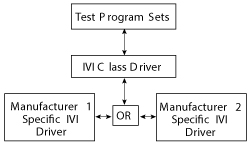
Figure 1 IVI drivers allow a common test program (TPS) to control instruments from many manufacturers.
Since SDSIs synthesize their measurement functions atop COTS hardware, they do not suffer from the same hardware and software obsolescence problems that affect traditional instruments. When a traditional instrument goes end of life (EOL), users are confronted with either buying additional units before production ceases or porting the TPS to the new instrument. With an SDSI, especially if its underlying hardware is modular, a new instrument can be synthesized on top of the replacement hardware, such that the APIs used by the TPSs are not affected. If the SDSI T&M apps (i.e., the SDSI instruments) are developed using object oriented techniques and design patterns, refactoring the T&M app to accommodate the replacement hardware and TPS interface will also be minimized. Hence, SDSIs address the problem of TPS portability, which the Army study shows leads to significant life cycle cost savings.
PROGRAMMING TRADITIONAL T&M INSTRUMENTS
With multiple manufacturers of test equipment and a need for automated control, the test industry developed a standard arbitration layer called the virtual instrument standard architecture (VISA). VISA allows software applications to communicate with an instrument regardless of the underlying hardware interfaces or equipment manufacturer.
Standard commands for programmable instruments (SCPI) was developed to standardize the command sets for specific instruments and, to some extent, across instruments. SCPI enables all compliant instruments within a given class (e.g., oscilloscopes) – even from different manufacturers – to respond to the same set of commands. Manufacturers usually extend the SCPI command set to their particular needs, since only a subset of SCPI commands are required to be compliant with the standard.4 To address the commands tailored to manufacturers yet provide a consistent programming interface to the end user, interchangeable virtual instrument (IVI) drivers were developed to standardize the controller software (see Figure 1).5
IVI drivers allow test programs to use standard drivers for a specific instrument type or class; this standard driver calls a second driver specific to the manufacturer’s equipment. A TPS developer writes only a single test program, and the IVI drivers handle the manufacturer-specific commands. If used correctly, test program developers can create robust, hardware-agnostic tests and TPSs using IVI. When TPSs only need core IVI driver functions, this system works well. However, different manufacturers often add functionality beyond the IVI drivers. These extensions, while useful, often result in TPS incompatibility when a different instrument is substituted for the original.
PROGRAMMING AN SDSI
An SDSI can be considered to be a tightly coupled collection of traditional instruments where each instrument is synthesized in the software using a combination of hardware and lower level software modules. The instrument modules are composed of T&M instrumentation software and firmware apps. Depending on the hardware configuration and the SDSI software design, the apps can run concurrently and independently. Each functions as a traditional instrument, so an SDSI appears to be a collection of traditional instruments to a remote test controller. Because of its system architecture, an SDSI can act as an instrument suite, a system controller and a TPS development environment.
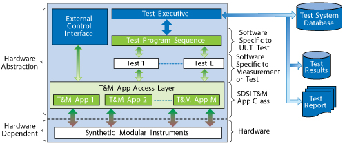
Figure 2 A system model for TPS portability.
To facilitate TPS portability, one of the primary development goals for an SDSI is creating a system where the same test programs can be run on the SDSI or using the traditional model of an external controller to the SDSI. Such control can be achieved via an open source API or app access layer that implements a VISA compliant interface into each app. Figure 2 shows a notional system model to accomplish TPS portability. The SDSI contains a TPS development environment that communicates through the API to the T&M apps. The API uses the VISA infrastructure to communicate between the T&M apps and the TPS. To analyze test results for a fleet of DUTs, the SDSI uses a measurement database that is accessible both to the API and the application infrastructure. The same development environment that exists on the SDSI is used on an external controller. It communicates to the apps through a copy of the APIs which are local to the external controller and which use the VISA infrastructure to communicate over a remote connection to the apps.
Because the VISA infrastructure is leveraged, the TPS programming methods that have been refined by the industry are used. Instead of modifying a TPS to accommodate the API, the API or a software translation layer can be developed so that the TPSs do not change.
RF MEASUREMENT EXAMPLE
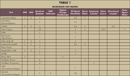
Verifying the functionality of microwave systems and components is not trivial because of the variety of unique tests and associated test equipment and setups. Table 1 shows the possible tests that are performed in the left column and the typical instruments used for the measurements across the top row. The numbers in the table represent the instruments that can be used to perform a given test. To illustrate, gain or attenuation can be measured with four different instrument setups: a vector network analyzer (VNA), scalar network analyzer (SNA), an RF signal generator and power meter, and an RF signal generator and spectrum analyzer. For the majority of the measurements, the instruments are combined with external components, such as couplers and filters. With an SDSI, many of these external elements can be synthesized with DSP processing (e.g., filters) or integrated with the hardware (e.g., couplers).
The signal-to-noise and distortion ratio (SINAD) is a good example to show this approach, since the measurement traditionally requires external filters (audio and notch, depending on the technique employed). These filters may be designed using numerical methods with digital processing, enabling the test environment to directly filter the data.
Sensitivity specifies how well a receiver demodulates low power signals. For analog frequency modulated (FM) systems, SINAD is typically used to quantify sensitivity.6 SINAD is computed as:
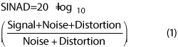
SINAD is determined by measuring the RMS value of a demodulated signal with and without the message signal.
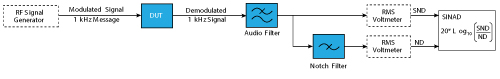
Figure 3 Measuring SINAD using a notch filter.
One traditional setup for measuring SINAD utilizes an RF signal generator, the DUT receiver, an audio filter, a notch filter and at least one RMS voltmeter (see Figure 3). Two RMS voltmeters (or a two channel voltmeter) must be used if the signals at the output of the audio filter and the notch filter are to be measured at the same time. The signal generator frequency modulates the signal with a 1 kHz message tone. The receiver demodulates the tone and transmits it through an audio lowpass filter. The output of the audio filter feeds a notch filter, centered at 1 kHz, and an RMS voltmeter. The first voltmeter measures the signal plus noise plus distortion (S+N+D). The notch filter suppresses the 1 kHz signal in the demodulated output, and this signal represents just the noise plus distortion (N+D). SINAD is computed from the ratio of the two measurements (equation 1).
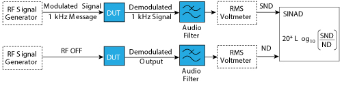
Figure 4 A simpler method for measuring SINAD, using a single audio filter and voltmeter and without a notch filter.
Another traditional method for measuring SINAD eliminates the notch filter by measuring the signal with the RF signal generator on and off (see Figure 4). This setup reduces the number of instruments and components to a single audio filter and RMS voltmeter. Initially the RF signal generator transmits the same FM modulated signal with a 1 kHz message tone. Received by the DUT receiver, the signal is demodulated, filtered with the audio filter and measured with the RMS voltmeter (i.e., S+N+D). With the RF output from the signal generator off, the resulting N+D signal is measured with the RMS voltmeter, and the SINAD is computed from the ratio of the two measurements.
The notch filter used with the first setup is a potential source of error; it may filter out noise and distortion close to the 1 kHz signal. If the notch filter is not tunable, the test range of the receiver is limited. The second method doesn’t have the same source of error, however the time delay between the S+N+D and N+D measurements may have different inaccuracies in the result.
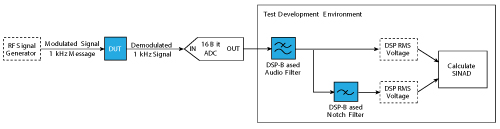
Figure 5 The SDSI approach to measuring SINAD with a notch filter (the configuration of Fig. 3).
To show the advantages of SDSI, the SINAD measurement examples mirror the previous test setups, even though other, DSP optimized, methods can be used. In the first method (see Figure 5), the SDSI RF signal generator app generates the analog FM signal with the 1 kHz tone. After being demodulated by the DUT receiver, the signal is digitized with a 16-bit analog-to-digital converter (ADC), which is controlled by a digitizer app. The output of the ADC is captured, formatted in volts and filtered with a DSP audio filter in the SDSI test environment. This is the S+N+D signal. The output of the DSP audio filter is also filtered with a DSP-based notch filter, creating the N+D signal. The RMS values of both signals are computed using the classic algorithm for computing RMS voltage with a set of discrete measurements,7
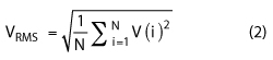
where N is the number of samples captured by the ADC. SINAD is then computed using equation (1).
The second method for the SDSI-based SINAD measurement, shown in Figure 6, uses the same technique as the second traditional method. Instead of using a notch filter, the output of the DUT is measured with the RF signal generator alternately on (the S+N+D signal) and off (N+D). While the figure shows two signal paths, the setup would only use a single RF signal generator and single ADC.
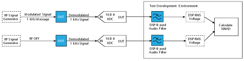
Figure 6 The SDSI implementation of the simpler SINAD measurement of Fig. 4.
The SDSI contains all required instruments within a single enclosure and uses numerical methods to calculate SINAD. With both SDSI implementations, the fixed function hardware is minimized. The analog filters (now DSP based), RMS voltmeter, DUT stimulus and signal capture are all contained within a single system and controlled through a single test development environment. By using DSP and numerical analysis techniques, the test program is hardware agnostic. If the underlying ADC changes, the test program remains the same. If the RF signal generator subsystem changes, the T&M app abstracts these changes and provides the same command interface to the TPS.
CONCLUSION
While multiple standards have attempted to reduce the problems of hardware obsolescence and interchangeability, significant challenges remain. An SDSI mitigates many of these through a T&M platform that is fundamentally software defined. Software interfaces remain the same to the TPS development environment while the underlying hardware and low-level software can be updated to improve performance or respond to obsolete hardware. This allows TPSs to migrate to new hardware without changing the underlying code. For new TPSs, development environments that utilize open source programming languages and numerical processing software packages enable developers to minimize the use of specialized, discrete hardware components. Open source languages and software enable better software compatibility. The same version of the development environment can be used on the SDSI itself or on an external system controller, if the SDSI is part of a larger ATS.
For systems designers, SDSIs reduce the test footprint, as many instruments are hosted in a single enclosure. Microwave measurements often require a variety of instruments and components. An SDSI reduces the equipment and ancillary hardware. In the SINAD measurement, the traditional method requires an RF signal generator, analog audio filter, analog notch filter and at least one RMS voltmeter. The SDSI method requires only the SDSI; the software within the SDSI performs the RF signal generation, audio and notch filtering and RMS voltage measurement.
References
- R. W. Lowdermilk and D. Carey, “Synthetic Instrumentation Eases ATE Obsolescence Woes,” COTS Journal, April 2014.
- David Carey, et al., “A Methodology for Enhancing Legacy TPS/ATS Sustainability via Employing Synthetic Instrumentation Technology,” IEEEAUTOTESTCON 2011.
- Synthetic Instrument Working Group, Meeting #2 Statements and Definitions, Dec. 11, 2004.
- SCPI Consortium, “Standard Commands for Programmable Instruments (SCPI) Volume 1: Syntax and Style,” May 1999.
- John Pasquarette, “Building Hardware-Independent Test Systems With IVI,” IEEE AUTOTESTCON 1998.
- I. Poole, “SINAD and SINAD Measurement for Radio Receivers,” www.radio-electronics.com/info/rf-technology-design/rf-noise-sensitivity/sinad.php.
- Martin Novotny and Milos Sedlacek, “RMS Value Measurement Based on Classical and Modified Digital Signal Processing Algorithms,” Measurement 41.3, 2008 pp. 236–250.
ABOUT THE AUTHORS
Alexis Allegra (alexisallegra@radxtech.com) is a Sr. Software Engineer with RADX Technologies Inc., a high-tech startup developing COTS SDSI technologies and products. Prior to RADX she worked at BAE Systems developing SI products. She received a BSEE from Tufts University and is working towards her MSEE at University of California San Diego with a focus on Digital Signal Processing.
David R. Carey (david.carey@wilkes.edu) is an Associate Professor of Electrical Engineering at Wilkes University in Wilkes-Barre PA. Dr. Carey is an internationally recognized expert and contributor in the Automatic Test Equipment (ATE) community. At Wilkes University, Dr. Carey teaches graduate and undergraduate courses that specifically address Automatic Test and related disciplines. Prior to Dr. Carey’s position at Wilkes University, he held the position of Chief of the Automated Test Equipment Development and Support Branch at Tobyhanna Army Depot. Dr. Carey received his PhD in Electrical and Computer Engineering from Clarkson University in Potsdam, NY.
Michael Spinali (michaelspinali@radxtech.com) is an Applications Engineer with RADX Technologies Inc. Spinali received his BSEE from San Diego State University and is working towards his MSEE with an emphasis in Digital Signal Processing.