
Scattering from electrically large objects invites discussions of Mie versus Rayleigh, shadows and diffraction, side scatter and backscatter. But one attribute remains infrequently discussed: forward or “front” scatter. Antipodal transmission, the continuation of the transmitted wave with fidelity to the other side, is a puzzle posed by blockage and failure to find a way to fully propagate waves around it. If robust front scatter is possible, and the surface orientation is not prescriptive, the object itself becomes hidden, cloaked by the mirage of the environment on the other side. The object is invisible. Such a phenomenon is not a natural occurrence and requires new technology to approximate and achieve realization.
While invisibility has always been a fantasy of fiction for many,1 engineering has developed limited alternatives with camouflage or stealth methods that absorb, reflect or directionally side-scatter waves to block the appearance of objects and render them less visible.2,3 Although many of these methods are ambiguously described as cloaking, they do not uniformly propagate front scatter without a preferential orientation, nor do they employ front scatter as a dominant mechanism. This article summarizes the results of the first true cloaking,4-6 demonstrating microwave cloaking with wideband performance, a dramatic decrease of side and backscatter, no preferred angular orientation in azimuth and robust front scatter.
Evanescent Surface Waves
Applications of the near field still render some surprising advantages, the most recent being associated with evanescent surface waves (ESW), also called plasmonics.7,8 ESWs are produced by impinging radiative traveling waves upon resonators and dielectrics in close electrical proximity to conductors, including other resonators. By their nature, ESWs dominate electromagnetic transmission with close resonators, usually with less than l/10 separation. Electromagnetic waves jump from one resonator to the next and remain on the surface. When such circuits are closely packed, they are also called metamaterials, whereas when they are more widely spaced, they have limited ESW transmission and are often called frequency selective surfaces.9 Metamaterial performance has previously been limited by the footprints and passband responses of the resonant structures used, which are typically split ring resonators. Such resonators are high Q but moderate in size, thus constraining their packing ability and limiting the efficiency of ESW transmission.
Fractals offer a unique opportunity as antennas and resonators, based on their multiband or broadband performance, small size, absence of LC components and efficiency.10-12 A good example with an excellent tradeoff of characteristics is a Minkowski fractal antenna,10 shown in Figure 1. The small footprint, about λ/8 on a side at the lowest resonant frequency, yields a highly efficient figure-eight dipole pattern with excellent polarization integrity. It also has multiple non-harmonic resonances that make a “passband meld” for broader bandwidth at the lower frequencies and a continuous broadband characteristic at higher frequencies.13-15 Thus, it has been used in close packed arrays, where ESWs are expected to be important.
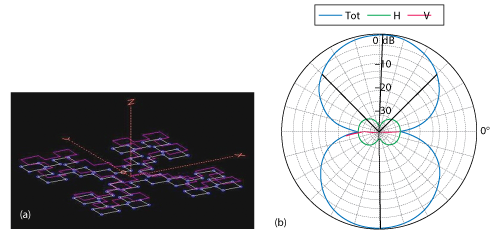
Figure 1 Minkowski loop fractal antenna model with amplitude of the two current maxima (a) and power pattern at lowest resonant frequency (b). Gain is within 0.2 dB of a dipole (copper losses included).
ESWs on a fractal array were first demonstrated in 2001.16 This is reproduced in Figure 2a, showing a 3 × 3 array of Minkowski fractal elements10 shaped as loops that is corporate fed with an element spacing of about λ/14. Each element falls within a footprint of approximately λ/8 at the lowest resonant frequency, and the array is offset slightly in azimuth to facilitate measurements on the plane. A metal backplane with roughly λ/8 air dielectric separation is behind the array, acting as the boundary condition required in plasmonics to give rise to ESWs.
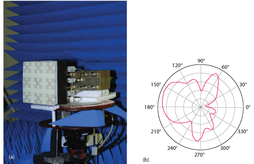
Figure 2 Fractal array (a) and power pattern with ESW lobes (b).
The azimuthal power pattern (see Figure 2b) is notable as showing super gain, but the interest here is focused on the 90 degree lobes. These lobes are caused by ESWs with intensities that rival those of the main lobe. The ESWs terminate at the array edge and become propagated radiated waves.
This demonstrates that for close packing, less than λ/10, ESW effects become appreciable in fractal metamaterial arrangements. It also shows that fractal structures, being far smaller than conventional designs and with no additional components attached, are natural to use if these effects are desired. The strong ESWs from these fractal metamaterials poses an opportunity to explore applications where ESWs may be needed, including cloaking.
Recipe for a Cloak
A cloaking mechanism must have the ability to passively guide far field traveling waves around an object or utilize ESWs to do so. Mirrors and lenses can be used to satisfy the former, but like the magicians’ invisibility illusion, they require very specific orientations or cannot entirely hide the blocked object. A cloak exploiting ESWs does not suffer from these hindrances.
Far field traveling waves impinge on a metal-backed metamaterial, producing ESWs. Care should be taken so that the resonators are wideband and closely packed (that is, a fractal metamaterial). The metamaterial array, which can be constructed in closed-surface layers, cloaks the object housed within the metal backing, for example, a metal cylinder. Any object of any composition may be considered cloaked inside that region. In addition, when properly spaced, the far field traveling wave reflects in backscatter and combines out of phase with its own impinging wave, yielding phase cancellation. There is also an attenuation of side scatter, as the ESW propagate on the surface, with little, if any, radiating wave in the far field.
If the cloak’s surface is closed, then at the antipodes of the impinging wave, the ESWs combine and produce a radiating traveling wave emerging from the plane of the surface in a reversal of their production. With no impinging radiating traveling wave on the “front” side, the produced radiating traveling wave does not have a second wave with which to combine and phase cancel. It constitutes front scatter of the wave which impinged from the opposite side, as shown in Figure 3.
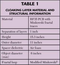
From a construction standpoint, a cloak is thus a closed surface structure composed of an array of fractal metamaterials, dielectric and a metal inner sheet. Figure 4 shows the outer layer of a simple two-layer cloak. Note the closely packed Minkowski fractal resonators, with a slight modification to the design for better packing. Material and structural information is given in Table 1.
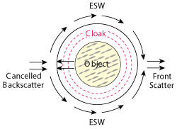
Figure 3 Cloak concept showing front and back scatter.
Other phenomena support this cloaking approach. For example, Chandran, et al.,17 reported highly reduced backscatter in metal-backed fractal surfaces, evidence for reflected and impinging radiated wave cancellation during backscatter. This reflection approach is an extrapolation of Jaumann absorbers, but the ease of realization with fractal structures was not anticipated.
A cloak attempt by Schurig, et al.,18 demonstrating a lossy, high Q device with moderate shadowing, is believed to result from transformational optics. Transformational optics must be considered a generic term without invoking a specific radiative transport mechanism, and ESW transport falls within that category. Yet the failure of that device to exclude diffraction as a mechanism for the attenuated, narrowband front scatter leaves the success of that as a bona fide cloak ambiguous.19
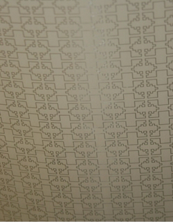
Figure 4 Outer layer of a simple two-layer cloak for microwaves.
Simple Cloak
Before advanced cloaks with precise imaging properties and visual light abilities (the fantasy of science fiction) are realized, it is necessary to demonstrate the ability to produce even the simple cloak illustrated in Figure 3. The approach is to use the microwave spectrum for construction simplicity of electrically thin cloak layers and a simple closed-surface geometry. First accomplished in 2008,4,5 this version of the simple cloak is sufficiently large to cloak 3D objects and to accomplish measurements with L-Band equipment.
Structural symmetry is not a restriction for cloaking: only a closed surface is needed to assure antipodal transmission of front scatter. However, for illustration, cylindrical symmetry limits the number of variables which might otherwise obscure understanding the ESW effects. Thus the results will be independent of the azimuthal rotation of the cloak itself: there is no specific requirement of preferred azimuthal alignment.
Measurement employs two log periodic antennas at sufficient separation so that the cloak fills the beam vertically.6 Since the horizontal portion of the beam is far wider, the cloak cannot fully fill the beam in that direction, so some coverage extends beyond the cloak, limiting the degree of blockage by an object to be cloaked and the dynamic range to roughly 25 dB or less. Polarization is taken as linear vertical, with the cloak oriented as a vertical cylinder. The cloak is electrically large, and the lower cutoff is limited to 700 MHz, where the height is approximately one wavelength.
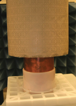
Figure 5 Placing the cloak over a metal cylinder (pipe) to be cloaked.
A vector network analyzer made the S12 measurements. All gain data is normalized to the direct path, that is, two antennas on opposite sides of the cloak’s center position (zero degrees in azimuth) with no blockage or cloak present. While these measurements are with the vertical polarization along the major axis of the cloak, the loop configuration of the fractal metamaterial resonators is agnostic to polarization orientation.
With no cloak or other objects present, this yields a 0 dB reference line at all frequencies. Then the cloak is introduced, using an internal metal pipe to be cloaked, as an example. This is shown in Figure 5 (see video at www.mwjournal.com/cloakingvideo1). The pipe alone blocks the signal by more than 10 dB at some frequencies. With the cloak covering it, however, front scatter gain is returned to 0 dB over a broad frequency range from about 700 to 1400 MHz. The cloak diverts transmission around the pipe and produces front scatter.
The cloak performs the same under rotation, with both antennas fixed on opposite sides. The rotation of the cloak in azimuth, with the antennas held stationary, produces virtually no change to the front scatter gain, as expected. There is no preferred orientation in azimuth. This, along with dramatic enhancement of front scatter and reduction of side and backscatter are the key characteristics of true cloaking.
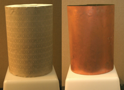
Figure 6 Cloak (left) and copper cylinder used as a control (right).
As in all experimental measurements, a control is essential. Here, it is the replacement of the entire cloak by a metallic ‘copper’ cylinder of the same size. In the video, this is done by covering the outer cloak layer with aluminum foil. For multiple measurements at different azimuthal angles of the two antennas, a copper-clad cylinder control is placed next to the cloak itself (see Figure 6).
The data shows the effects of the cloak on front scatter and backscatter. Starting with the control ‘copper’ cylinder directly blocking the direct path between the two antennas, we expect the front scatter to be greatly reduced, and the backscatter to be greatly enhanced from specular reflection. In such measurements the antennas are on opposite sides of the cloak or copper for front scatter, and next to each other, on the same side, for backscatter. Again, using the direct path normalized at 0 dB, the response of the control for front and backscatter is shown in Figure 7. As expected, backscatter is present, approaching a gain nearly that of the direct path, while the front scatter is significantly lower.
Placing a cloak with the pipe as an object in place of the control cylinder yields the exact opposite; backscatter is reduced and front scatter is enhanced (see Figure 8). Front scatter now closely tracks the direct path intensity over a frequency range of approximately 700 to 1400 MHz, a 2:1 bandwidth. In other words, we are are “seeing through to the other side” with excellent amplitude fidelity. Note that the backscatter is dramatically reduced from about 700 to 950 MHz, with a minimum at about 825 MHz. The Q is higher (about 30 percent bandwidth) for the backscatter because the reflected traveling wave has only one main layer to reflect from; additional fractal metamaterial layers would substantially increase the bandwidth to minimize back scatter.
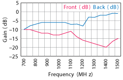
Figure 7 Front and back scatter measurements of the copper cylinder used as the control.
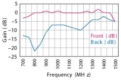
Figure 8 Front and back scatter measurements of the cloak with internal pipe.
With the minimum backscatter at 825 MHz, a full azimuthal scan of the antenna at that frequency is useful to compare the overall scattering behavior of the cloak versus the control. Because the log periodic antennas have wide beams, baffles were used to suppress off-angle coupling and measurements were done by moving one antenna in 30 degree steps, starting with the direct path at zero degrees. The cloak and control, when measured, do not change their positions; only the antenna angles relative to the center point of the cloak’s placement change.
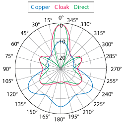
Figure 9 Azimuthal scattering from the control and the cloak.
To understand how these measurements relate to scattering, side scatter is sampled at angles near 90° and 270°, while backscatter is near 180°; and front scatter is near 0° in azimuth. The values at 180° are approximated to be 183° and 177°, respectively, as the baffle prevents the two antennas from being placed at the same position simultaneously.
The two antennas without any cloak or obstruction are measured over the full azimuthal range of their differential angular placement (direct). This represents the response of the antenna system, with the baffles and other (minor) reflections present, without a blocking object, cloak or control. Next, at each differential azimuth angle, the cylinder (copper) and then cloak-on-pipe (cloak) are measured, yielding a total of three measurements per azimuth sample. This allows an unbiased comparison of the cloak and copper. A polar plot of the data is shown in Figure 9.
The cloak scattering response closely matches that of the azimuthal response of the antennas alone, without any cloak or obstructions. The front, back and side scatter all act as if there is nothing there. In contrast, the copper control shows very little front scatter (as in Figure 6), and substantial side and back scatter. The lobe-like pattern is produced by the variation in response from baffle placement with changing azimuth. A marked difference between the control and the cloak, with a close match of the cloak to the direct measurement, is compelling evidence for cloaking by the enhancement of front scatter and the reduction of side and backscatter.
Next Steps
This simple cloak establishes the value of using ESWs for cloaking with fractal arrays as the enablers. With cloaking realized, questions and issues become varied and numerous. In fact many have already been addressed by the author and will be discussed in future publications. It is helpful to enumerate these issues as next steps.
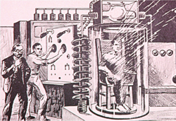
Sidebar 1 1930s pulp sci-fi illustration shows a man in a cylinder dematerializing and becoming invisible.
Large object, thin cloak: Much larger microwave cloaks have been built and function successfully. The largest cloak yet devised successfully cloaked a person, realizing H.G. Well’s historic fantasy.6 The sidebar (see below) describes that effort. The cloak is a thin skin on a large cloak because the cloaking layers depend on wavelength separation, not scaled-size ratios.
Tunneling and object-view non reciprocity: Seeing out of a cloak from inside is not the reciprocal action of external cloaking. However, having a copper or metal barrier certainly stops the action. This has been overcome with a fractal screen as the inside barrier rather than a solid metal sheet.20
Reduced backscatter and optimization: Cloaking may achieve wideband and significant backscatter reduction by optimizing the cloak parameters and by adding layers. This awaits a defined need.
Diverted imaging: Antipodal transmission implies origin symmetry of the image. Whether this will limit cloaking, ultimately, as an optical camouflage method will depend on the understanding of cloaking as an imaging system, rather than the radiometric one discussed here.
Non-symmetric surface cloaking: Surface symmetry (as in cylinders or spheres) is not a requirement for cloaking and cloaking with asymmetric surfaces has been demonstrated.20
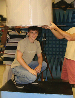
Sidebar 2 Cloaking of an engineering intern.
Visual light and infrared cloaking: The patterning of resonators is easily achieved at infrared wavelengths but this may prove challenging at optical wavelengths for any large surface. Additional manufacturing developments may warrant interest in the “Harry Potter” effect when this is achieved.
SIDEBAR
First Person Cloaked
To the general public, rendering a person invisible is the stuff of Star Trek, Harry Potter and H.G. Wells (see Sidebar 1). But beyond the dreams and fantasy, the quest for human invisibility poses technical challenges and compelling examples of electromagnetics. Furthermore, it sets the bar for future cloaking efforts.
In August 2012, to commemorate the issuance of the world's first true invisibility cloak patent and serve as a symbol that the path of this new field rests on the shoulders of those who grew up during the wireless revolution, the team at Fractal Antenna Systems scaled up a two-layer microwave cloak to make an engineering intern disappear (see Sidebar 2).
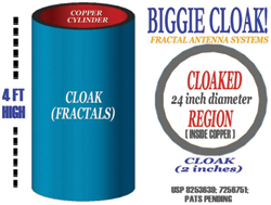
The human cloak, illustrated in Sidebar 3, is electrically larger in size, has a larger cloaking volume, a greater signal to noise ratio and higher fidelity, compared with the smaller cloaks previously built. It simply consists of a thin copper cylinder, two fractal metamaterial layers, air foam spacers and an RF transparent support structure.
Sidebar 4a shows the direct path with no obstruction (dotted line) compared with the intern crouched and blocking the path of radiation (solid line). Sidebar 4b compares the same direct path to the path with the cloak placed over the crouching intern. Note the transmission "through" the intern (solid line), demonstrating ESW-enabled front scatter with the cloak on. The intern has "disappeared" over a broad frequency range centered at 1 GHz.
Visit www.mwjournal.com/cloaking for more demos.
CONCLUSION
The first true cloaking system uses ESWs to produce substantial front scatter over a wide bandwidth and reduced backscatter and side scatter, with no preferential angular orientation of the cloak’s surface. Far from science fiction, the world of invisibility looms ahead, neither blocked by an absence of mechanism nor totally transparent in its use and implications.
Sidebar 3 Design of a large cloak.
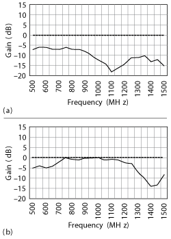
Sidebar 4 Scattering responses of the uncloaked intern compared with the direct path (a) and the cloaked intern compared with the direct path (b).
References
- H. G. Wells, “The Invisible Man,” Pearson, London, 1897.
- K. Vinoy and R. Jha, “Radar Absorbing Materials,” Kluwer, Boston, 1996.
- G. Ruck, D. Barrick, W. Stuart and C. Krichbaum, “Radar Cross Section Handbook,” Plenum, New York, 1970.
- N. Cohen, “Fractal Antennas and Fractal Resonators,” U.S. Patent 7,256,751, 2007.
- N. Cohen, “Wideband Electromagnetic Invisibility Cloak,” U.S. Patent 8,253,639, 2012.
- N. Cohen, “Body-Sized Wideband High Fidelity Invisibility Cloak,” Fractals, Vol. 20, November 2012, pp. 227–232.
- R Maier, Plasmonics, Springer, New York, 2007.
- S. Zoughi, A. Sihvola and A. Vinogradov, “Metamaterials and Plasmonics: Fundamentals, Modelling, Applications,” Springer, Dordtrecht, 2008.
- B. Munk, “Metamaterials: Critique and Alternatives,” Springer, Dordtrecht, 2008.
- N. Cohen, “Fractal Antennas Part 1”, Communications Quarterly, Vol. 5, No. 3, Summer 1995, pp. 7–22.
- N. Cohen, “Fractal Antennas and Fractal Resonators,” U.S. Patent 6,452,553, 2002.
- A. R. Harish, A. Agarwal, N. Kuchhal and V. Jain, “Compact Loop Antennas and Arrays,” Proceedings of the International Conference on Antenna Technologies, 2005, pp. 531-535.
- N. Cohen, “Fractal Antennas Part 2,” Communications Quarterly, Vol. 6, No. 3, Summer 1996, pp. 53–66.
- N. Cohen, “Practical Introduction to Fractals: Antennas and Beyond Part 1,” Proceedings of the Radio Club of America, Spring 2014, pp. 12–18.
- A. Raveendran, “A Study on Minkowski Fractal Wideband and Multiband Antenna,” M.S. thesis, Texas A&M University, 2012.
- N. Cohen and R. Hohlfeld, “Close-Packed Fractal Antenna Array,” AFRL/SNRT Contracts F30602-02-M-V042V-034, 2002.
- A. R. Chandran, T. Matthew, C. K. Aanandan, P. Monahan and K. Vasudevan, “Low Backscattered Dual-Polarized Metallo-Dielectric Structure Based on Sierpinski Carpet,” Microwave and Optical Technology Letters, Vol. 40, No. 3, February 2004, pp. 246–248.
- D. Schurig, J.J. Mock, B.J. Justice, S. A. Cummer,J.B. Pendry, A.F. Starr and D.R. Smith, “Metamaterial Electromagnetic Cloak at Microwave Frequencies,” Science, Vol. 314, No. 5801, November 2006, pp. 977–980.
- J. B. Pendry, D. R. Smith and D. Schurig, “Electromagnetic Cloaking System.” U.S. patent application 20080024792 (examiner’s comments in rejection), 2008.
- N. Cohen, “Additional Advances in Cloaking Using Fractal Resonators,” in preparation, 2015.