
Long-term evolution (LTE) advanced carrier aggregation trends are changing the design game for smartphones. The insatiable consumer demand for more capable smartphones and the rush to get them to market quicker is creating a nightmare of design headaches for mobile phone manufacturers. They must accommodate skyrocketing consumer market demands for the latest generation phones, while handling rapidly expanding and changing wireless communications protocols, fewer dropped calls, wider bandwidths, and better voice and data quality levels.
Recognizing this, the MIPI® Alliance (MIPI) was formed over a decade ago to benefit the mobile smartphone industry by establishing standard hardware and software interfaces and encourage their adoption throughout the mobile telecommunications ecosystem. It seeks to reduce fragmentation caused by too many proprietary industry interfaces that are incompatible, yet are not typically differentiated from each other.
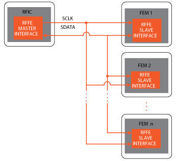
Figure 1 Simplified RF front end interface model of the MIPI RFFE standard. Source: National Instruments.
There’s no question that consumer demand for smartphones is insatiable. Many market estimates are that smartphone users change their devices an average of once every two years to acquire more advanced units with greater capabilities. According to a recent study by ABI Research, some 800 million Android smartphones and 300 million Apple iPhones were in active use at the end of last year, while IDC Research forecasts that total smartphone sales will reach 1.7 billion units by 2017, up from 2013’s 1 billion units.
The evolution of wireless communications from 2G, 2.5G, 3G, and 3.5G to 4G technologies is putting a strain on the smartphone’s RF design, particularly the RF front end (RFFE). The continuing emphasis on smaller form factors with higher efficiencies, lower power consumption, faster data rates and higher bandwidths is giving rise to more complex RF designs. Actual voice conversations supported by smartphones are but a small fraction of their vast capabilities. These include the integration of high-quality video cameras, music and video playback, texting, gaming and a multitude of different touchscreen applications.
Incompatibility leads to redundant engineering investment and higher design costs (but not higher margins/value). The MIPI goal is to reduce fragmentation with a simplified RF front end model (see Figure 1). This provides attractive convergence targets that have technical and intellectual property (IP) rights benefits over proprietary alternatives. The first version (version 1.0) of the MIPI RFFE standard was adopted back in 2010. While not providing a one-size-fits-all solution, it has attracted wide industry interest because it broadly accommodates the many existing standard bus interfaces, such as the serial-peripheral interface (SPI) and the I2C bus standards. The former cannot handle much more than 10 MHz data rates and lacks protocol-level standardization, while the latter is limited to about 1 MHz which is unsuitable for meeting RFFE standard requirements.
A Need for Unification
The RFFE standard addresses the need for unifying multi-band and multi-radio support. It aims to unify the RF front end by providing a bus interface between a mobile device’s transceiver, having a myriad of front end functions, to an internal device. This challenges both wireless communications carriers and mobile terminal makers. Carriers demand support for their increasing number of selected frequency and roaming bands, while mobile terminal makers prefer a minimum number of different designs to maximize their sales and profit margins.1 It is exacerbated by the fact that radio access technologies (RAT) are not supported globally in a standardized manner. Historically, frequency spectrum allocations have been specific to each country and are typically controlled by local governments. Waiting in the wings and ready for deployment is the advanced LTE (LTE-Advanced) standard put forth by the Third Generation Partnership Project (3GPP). It offers a significant upgrade to the LTE standard, and features up to 40 frequency bands,2,3 while analysts are predicting up to 50 frequency bands within the next couple of years. This will make mobile device front end design even more complex. “We used to have four RAT bands with 4G LTE. Now we have 40 and it is rapidly exploding,” says Rick Wietfeldt of Qualcomm. Wietfeldt is chairman of the Technical Steering Group of the MIPI Alliance.
Seeing that front ends were becoming more complex in handling multi-band and multi-mode radio transmissions with no standard control mechanism in existence, the International Wireless Industry Consortium (IWPC) challenged MIPI to develop a standard. The MIPI RFFE standard has been widely adopted by the industry and has become the pre-eminent standard for RF front end control.
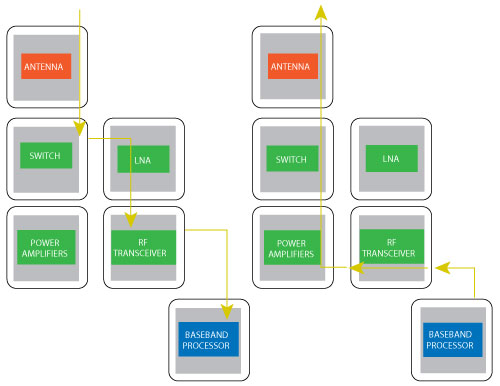
Figure 2 The MIPI RFFE interface. Source: The MIPI Alliance.
A Robust RFFE Bus
The RFFE interface control bus can be used for (but is not limited to) controlling RF front end devices like antennas, power amplifiers, switches and filters. It is a two-wire system defining one line for system clock and another for the bidirectional system data. It uses a third common line for voltage referencing and interface power. RFFE is a single-master system that avoids timing uncertainties inherent with bus arbitration (see Figure 2). The 26 MHz bus operates from either 1.8 or 1.2 V and can be implemented in standard CMOS. The signaling levels employ hysteresis for even greater noise immunity and is slew-rate controlled for improved electromagnetic interference (EMI) mitigation.
An objective of the RFFE standard is to keep silicon implementation as simple as possible and as small as practical; hence, the MIPI standard specifies just a three-pin device that is multi-drop capable and scalable using one master and 15 slaves per master. Each master circuit may be designed using about 5,000 gates and slaves may take as few as 500 gates. Other specifications include a low latency of less than 1 µs, broadcast message capability to multiple slaves and user-defined IDs for write commands. The RFFE standard is based on the system power management interface (SPMI) specification but is simplified for front end devices by removing the multi-master capability and certain other SPMI features.4
A number of integrated all-silicon approaches have been demonstrated, as well as individual-function IC solutions. The challenge is to provide enough flexibility for the smartphone manufacturer to distinguish itself in the market from other mobile phone competitors’ products. The research analyst Heavy Reading predicts that LTE RF issues will create large opportunities for IC RF front end chip makers to address the needs of active antennas, tuning circuits and other RF components for future LTE devices. It cites Qualcomm’s RF360 front end IC solution that supports up to 40 bands as an example of what’s to come.
Silicon Abounds
Companies are readying themselves for new-generation 2.4 and 5 GHz 5G Wi-Fi mobile phones. Using custom design approaches, companies have demonstrated discrete implementations of completely integrated RF front end system-in-package (SiP) using CMOS, gallium-arsenide (GaAs), silicon-germanium (SiGe), silicon-on-insulator (SOI), and BiCMOS processes.
Major IC vendors offer various RFFE interface chips for power, RF communications, control and transceiver functions in standard, custom, FPGA, IP and other package forms. These devices include: front end tuning circuits, buck-boost DC-DC converters for 3G and 4G LTE RF power amplifiers, general-purpose output expanders with an RFFE host interface, power amplifiers, antenna switches, and front end configurable matching networks. Other companies have introduced RFFE compatible custom IP cores using field-programmable gate arrays (FPGA). RFFE hardware and software development tools are also on the market. At the academic level, several universities worldwide have shown that RFFE compliant ICs are possible for any number of interface functions. These include camera, cognitive radio, display, power amplifier and ultra-wideband, front end interfaces.
Conclusion
The MIPI RFFE bus standard addresses the need for a simplified front end network interface design, driven by the soaring complexity of mobile communications LTE smartphone technologies. MIPI is also working on developing other interface standards with working groups such as the BIF battery interface, the CSI camera interface, the DigRF interface, the Debug standard for tracing and debugging, the DSI display signal interface, the LLI low-latency interface, the PHY physical layer interface, the SLIMbus serial low power interchip Media bus, the SPMI system power management interface, and the UniPro Unified Protocol standard.
Membership in MIPI has rapidly grown to more than 260 member companies. It is not surprising that major semiconductor IC manufacturers form MIPI’s board of directors. The membership includes a large number of IC chip makers, hardware and software product manufacturers, telecommunications computer companies, test equipment houses, and academic institutions. The objective of MIPI is to enlist the membership of companies, organizations and academic institutions; all with an interest in simplifying mobile communications device designs. However, solutions must be robust enough to allow those interested members the freedom of choice in their design approaches, as dictated by market and consumer demands.6-10
References
- P. Gammel, “Turning Complexity into Breakthrough Simplicity,” Microwave Journal, Vol. 56, No. 8, August 2013, p. 56.
- Third Generation Partnership Project (3GPP), http://3gpp.org.
- L. Frenzel “An Introduction to LTE-Advanced: The Real 4G,” Electronic Design Magazine,February 2013, pp. 32-38.
- V. Wilkerson and G. Hueber, “Unification in the RF Front-End: The New MIPI Standard,” EE Times, November 2010, www.eetimes.com/document.asp?doc_id=1278402.
- R. Whatley, T. Ranta and D. Kelly “RF Front-End Tunability for LTE Handset Applications,” IEEE Compound Semiconductor Integrated Circuit Symposium, October 2010, pp. 1-4.
- D. Kim, S.J. Lee, D.H. Kim and K. Cho, “Design of a D-PHY Chip for Mobile Display Interface Supporting MIPI Standard,” IEEE International Conference on Consumer Electronics,January 2012, pp. 660-661.
- H.Motoyama, Y. Jingu, T. Kimura, A. Lawrenson and J.C. Clifton “Stacked FET Structure for Multi-Band Mobile Terminal Power Amplifier Module,” IEEE Microwave Theory and Techniques Society Symposium Digest, June 2013, pp. 1-4.
- J. Shao and X. Ling, “Design and Implementation of Cognitive Radio Model Based on FPGA,” International Conference on Computer Application and System Modeling, Vol. 2, October 2010, pp. 415-418.
- P. Simitakis, Y. Papanos and E.S Kytonaki “Design of a Low-Voltage Low-Power 3.1-10.6 GHz UWB RF Front-End in a CMOS 65-nm Technology,” IEEE Transactions on Circuits and Systems II: Express Briefs, Vol. 57, No. 11, November 2010, pp. 833-837.
- N. Deltimple, E. Kerherve, Y. Deval, D. Belot and P. Jarry, “Design of a SiGe Reconfigurable Power Amplifier for RF Applications: Device and Multi-Standard Considerations,” 13th IEEE International Conference on Electronics, Circuits and Systems, December 2006, pp. 331-334.