
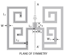
Figure 1 Quad-mode SLR configuration.
A miniaturized tri-band bandpass filter (BPF) design uses a quad-mode stub-loaded resonator (SLR). Its characteristics are investigated by using even- and odd-mode analysis. Without occupying additional area, tapped side-coupled open-loop resonators are used to induce the third passband. The three passbands are designed at 1.57, 3.5 and 5.2 GHz for GPS, WiMAX and WLAN applications. The center frequencies of the three passbands are independently controlled and their bandwidths tuned by the filter dimensions. In addition, four transmission zeros improve selectivity.
The multi-band planar bandpass filter is a key component in a modern wireless communication system because of its compact size, high selectivity and low integration cost. As a result, the multi-band bandpass filter is extensively investigated and various design approaches have been reported.1-10
Tri-band filters are commonly achieved with cascaded stepped-impedance resonators (SIR),1,2 but are relatively large. Composite configurations consisting of three split-ring resonators have also been used.3 To reduce size, a combination of one set of half-wavelength resonators and one set of SLRs has been proposed.4 One set of tri-section SIRs has also been utilized;5,6 however, the dependence of the resonant frequencies of the SIRs complicates the filter design. Recently, tri-band BPFs have been constructed using a SLR with a defected ground structure (DGS) resonator7 and a square ring loaded resonator.8,9
In this article, a compact tri-band BPF using a quad-mode SLR and a pair of side-coupled resonators is described. The former generates the first and second passbands and the latter generates the third passband without increasing circuit size. The three passbands are conveniently tuned by properly controlling the dimensions of the filter. Four transmission zeros improve selectivity and stopband suppression.
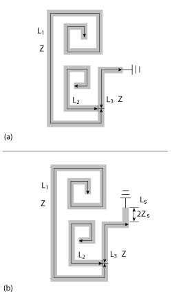
Figure 2 Equivalent circuit; odd-mode (a), even-mode (b).
ANALYSIS
As shown in Figure 1, the quad-mode SLR consists of one pair of spiral open-circuited stubs, with length (L2) and width (W) connected by a uniform impedance resonator (UIR) with length (2L1 + 2L3) and width (W). One short-circuited stub (LS, WS) located along the symmetrical plane is added to provide dual-mode characteristics. Since it is symmetrical to the A-A' plane, even- and odd-mode theory is adopted to analyze the resonator structure. The corresponding odd-mode and even-mode equivalent circuits are shown in Figures 2a and b, respectively. In Figure 2a, the odd-mode equivalent circuit contains two resonant circuits and the resonant frequencies are determined by:
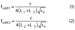
where c is speed of the light in free space and εe denotes the effective dielectric constant of the substrate. For the even-mode excitation, the required resonant frequencies are determined by:
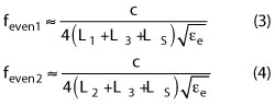
Equations 3 and 4 are based on the special case where 2ZS = Z. From equations 1-4, it is apparent that adjusting the spiral open-circuited stub length, L2, has no influence on the resonant frequencies feven1 and fodd1, whereas it leads to a variation of the resonant frequencies feven2 and fodd2. As shown in Figure 3, the high resonant frequencies feven2 and fodd2 move towards the lower frequency, whereas the resonant frequencies feven1 and fodd1 remain relatively stationary, as the open-circuited stub length (L2) increases. Figure 4 shows that the quad-mode resonant frequencies decrease with larger L3. Also, from the equations, the short-circuited stub length, LS, changes only the even-mode frequencies.
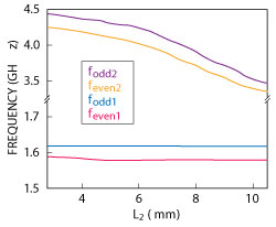
Figure 3 Even-/odd-mode frequencies with varied L2.
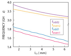
Figure 4 Even-/odd-mode mode frequencies with varied L3.
RESULTS
A compact tri-band BPF is shown in Figure 5. It consists of the quad-mode SLR and a pair of side-coupled resonators with length (L4+L5) and width (W). As previously mentioned, the former is used to generate the first and second passbands and the latter generates the third passband for the tri-band BPF design. Based on the above analysis, it can be seen that the first passband (formed by feven1 and fodd1) is determined by L1+L3, and its bandwidth is tuned by LS. Similarly, the second passband (formed by feven2 and fodd2) is controlled by tuning L2+L3, and its bandwidth is also changed by LS. The distance between the center frequencies of two passbands is controlled by the difference between L1 and L2. As shown in Figure 6, as LS increases, the even mode frequencies (feven1 and feven2) shift lower in frequency, while the odd mode frequencies (fodd1 and fodd2) are fixed. Thus, the bandwidths of the first and second passbands can be tuned by the length of LS. The bandwidth of the third passband can be tuned by the gap (g2), as shown in Figure 6. Also, the pair of side-coupled resonators encircles the SLR and serves as a part of the feed-line structure for compactness.
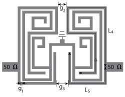
Figure 5 Tri-band BPF configuration.
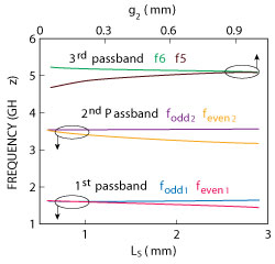
Figure 6 Even-/odd-mode mode frequencies with varied LS (colored lines) and resonant frequencies with varied g2 (black lines).
The demonstration tri-band BPF is fabricated on a substrate with a relative dielectric constant of 3.5 and a thickness of 0.76 mm. The parameters are L1=24.6 mm, L2=10 mm, L3=4.2 mm, L4=26.3 mm, L5=9 mm, LS=1.15 mm, W=0.2 mm, WS=0.6 mm, g1=0.2 mm, g2=0.58 mm, g3=1.7 mm.
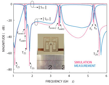
Figure 7 Simulated and measured frequency responses; photograph of fabricated filter (inset).
Figure 7 shows good agreement between simulated and measured results. Fractional bandwidths are about 6.3 percent at 1.57 GHz, 3.7 percent at 3.5 GHz, and 4.3 percent at 5.2 GHz, respectively. Measured minimum insertion losses within the three passbands are 1.4, 1.25 and 1.28 dB, respectively. Four transmission zeros located at 1.04, 1.69, 1.84 and 5.65 GHz improve filter selectivity. Also shown in Figure 7 is a photograph of the fabricated BPF. Its overall size is about 0.092λg by 0.091λg, where λg is the guided wavelength at the center frequency of the first passband.
CONCLUSION
A miniaturized tri-band BPF for GPS, WiMAX and WLAN applications using a quad-mode SLR is introduced and analyzed. Center frequencies and bandwidths of the three passbands are adjusted by controlling the filter dimensions. This compact tri-band filter with simple topology is particularly suitable for multi-band and multi-service applications in wireless communication systems.
ACKNOWLEDGMENTS
This work was supported by the National Science Foundation of China, (No. 61061001) and International Cooperation Funds and Science and Technology Innovation Team of Jiangxi Province of China (No. 20121BDH80015, 20122BCB24025).
References
- B.J. Chen, T.M. Shen and R.B. Wu, “Design of Tri-Band Filters With Improved Band Allocation,” IEEE Transactions on Microwave Theory and Techniques, Vol. 57, No. 7, July 2009, pp. 1790-1797.
- R. Moussa, V.K. Palukuru, A.K. Sowpati, M. Essaaidi, H. Jantunen and M. Aghoutane, “Tri-Bandpass Filter Based on Two Stepped Impedance Resonators,” Microwave and Optical Technology Letters, Vol. 54, No. 7, July 2012, pp. 1765-1768.
- R.H. Geschke, B. Jokanovic and P. Meyer, “Filter Parameter Extraction for Triple-Band Composite Split-Ring Resonators and Filters,” IEEE Transactions on Microwave Theory and Techniques, Vol. 59, No. 6, June 2011, pp. 1500-1508.
- X.Y. Zhang, Q. Xue and B.J. Hu, “Planar Tri-Band Bandpass Filter With Compact Size,” IEEE Microwave and Wireless Components Letters, Vol. 20, No. 5, May 2010, pp. 262-264.
- C.I.G. Hsu, C.H. Lee and Y.H. Hsieh, “Tri-Band Bandpass Filter With Sharp Passband Skirts Designed Using Tri-Section SIRs,” IEEE Microwave and Wireless Components Letters, Vol. 18, No. 1, January 2008, pp. 19-21.
- Q.X. Chu and X.M. Lin, “Advanced Triple-Band Bandpass Filter Using Tri-Section SIR,” Electronics Letters, Vol. 44, No. 4, February 2008, pp. 295-296.
- X. Lai, C.H. Liang, H. Di and B. Wu, “Design of Tri-Band Filter Based on Stub Loaded Resonator and DGS Resonator,” IEEE Microwave and Wireless Components Letters, Vol. 20, No. 5, May 2010, pp. 265-267.
- J.Z. Chen, N. Wang, Y. He and C.H. Liang, “Fourth-Order Tri-Band Bandpass Filter Using Square Ring Loaded Resonators,” Electronics Letters, Vol. 47, No. 15, July 2011, pp. 858-859.
- M.T. Doan, W.Q. Che and W.J. Feng, “Tri-Band Bandpass Filter Using Square Ring Short Stub Loaded Resonators,” Electronics Letters, Vol. 48, No. 2, January 2012, pp. 106-107.
- Q.X. Chu, X.H. Wu and F.C. Chen, “Novel Compact Tri-Band Bandpass Filter With Controllable Bandwidths,” IEEE and Microwave Wireless Components Letters, Vol. 21, No. 12, December 2011, pp. 655-657.