
A new experimental approach to teaching antenna and microwave topics is realized with general-purpose, off-the-shelf devices and is suitable for different educational levels and scenarios, from children to high-school students, from science shows to under-graduate and graduate courses. Its flexibility enables efficient budgeting for educational activities that can be easily tailored to meet learning needs at all education levels and encourage young people to pursue science, technology, engineering and mathematics (STEM) careers.
Figure 1 System schematic.
Microwaves, electromagnetic theory, antennas and propagation are standard topics for undergraduate and graduate courses in electronics and telecommunications,1 while the growing use of microwave devices and services, such as mobile phones, car navigators and satellite broadcasting is having an increasing impact on people’s lives.2 There continues to be, however, a lack of understanding of basic microwave and electromagnetic (EM) field principles.3 There are two main reasons; first, the equations describing EM phenomena (e.g., Maxwell equations and the wave equation) are often considered complex by most students and second, the effects associated with microwaves are not directly visible by the human eye. The consequences are a general misconception about microwaves and a limitation in the number of students deciding to follow an educational track in microwaves and EM fields.4
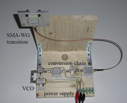
Figure 2 Transmit section.
This problem has been addressed in recent years with courses to engage and motivate students through the use of alternative lectures5,6 and by re-addressing the most critical points of classical lectures.3,7-9 Systems have been proposed to support microwave and EM theory comprehension based on software-aided approaches10-12 or through experimental activities.12,13 These usually target specific types of students. Software-aided approaches (usually best suited for high-level education) and experimental approaches (suitable to different levels according to the experimental setup) address only a limited range of educational scenarios.
This article describes a new experimental approach, preferred over software-aided lectures because it is believed to be the most convenient and easiest way to explain EM phenomena.14-16 Two main aspects distinguish it from other experimental approaches recently proposed.17-21 First, the experiments are based on off-the-shelf devices, easily purchased and prepared by most high-school and university laboratories, even with limited budgets. Second, since it is expected to be used at several different educational levels – from children to high-school students, from science shows to under-graduate and graduate students – it is designed to be very general, covering several different topics. In this way, it is possible to select the most suitable experiments. In addition, each experiment is explained using both quantitative and qualitative feedback, the former best suited for high-school, under-graduate and graduate students and the latter best suited for children and for science shows.
This flexible, inexpensive and experimental system is easily adapted to different scenarios.22 It has been used since 2010 for dissemination and educational purposes, obtaining great interest from general public (science shows, children, high-school students) and from undergraduate students.
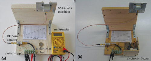
Figure 3 Receive section with multimeter (a) or with buzzer (b).
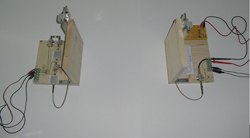
Figure 4 Basic setup.
Description
Figure 1 is the system schematic, while Figures 2 and 3 are photographs of the system itself. A voltage-controlled oscillator (VCO) generates a low-band signal (tunable from 1.5 to 2.5 GHz). For these frequencies, inexpensive devices are readily obtainable. The signal is brought to the high-band (6 to 10 GHz, more convenient for the intended experiments) by means of two passive frequency doublers and two power amplifiers and then routed to an SMA-waveguide (SMA-WG) transition that also acts as the transmitting antenna (see Figure 2). By using the proper SMA-WG transition (WR112) it is possible to have the entire high band within the fundamental-mode bandwidth of transition. After propagating through air, the signal is received by a twin SMA-WG transition and rectified by a power detector (see Figure 3). The output voltage of the power detector is read by a digital multi-meter and translated into a power level according to its response curve. Alternatively, the detector signal is read with an in-house designed front end that drives an electronic buzzer. If used for undergraduate and graduate courses, the digital multi-meter is best suited because it allows for quantitative study of the EM phenomena, whereas the electronic buzzer is better for children and for science shows. Each device is selected for compatibility with all other devices in terms of input/output connectors, power supply voltages, input/output powers and operating frequencies.
Figure 5 Measured power (diamonds) and fitting quadratic curve (solid line).
The system is designed to be inexpensive. In particular, all active devices are powered with a +5 V DC power supply. Only the VCO may require an additional DC voltage to tune the frequency of the generated signal, if required. With no tuning voltage (i.e, zero volts), the VCO signal is around 1.5 GHz and, therefore, the output signal after the multipliers is around 6 GHz.
All the devices in the transmit and the receive sections are mounted on L-shaped wooden supports where the horizontal plane is used for the electronic devices while the vertical plane is used to hang the SMA-WG transition, that can also rotate around the hanging bolt in order to change linear polarization. The entire setup is inexpensive and easy to assemble with normal DIY skills. All devices are readily available. The only (not mandatory) device requiring in-house development is the front end for the buzzer; however, it is simple as it requires basic skills taught in electronic and telecommunication courses and some high-school programs. Thus, it provides a great opportunity to further stimulate interest in scientific topics.23
Antenna and Propagation
This system can be used to demonstrate several different concepts related to antennas and propagation such as 1) the Friis formula, 2) polarization, 3) propagation through materials, 4) radiation patterns and 5) radar.
Friis Formula
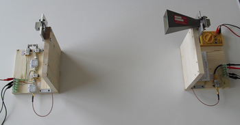
Figure 6 Horn antenna.
The Friis formula is used to determine the loss due to free-space attenuation experienced by a microwave link.24 With the digital multi-meter it is possible to derive the Friis formula, and this is particularly useful for high-school, undergraduate and graduate students. Otherwise, the electronic buzzer returns a qualitative feedback given by the volume of the sound generated by the buzzer. This is attractive for children and science shows.
As an example, the transmitting and receiving sections are placed in front of each other at a distance of around 0.5 m (see Figure 4) and the VCO is tuned to around 8 GHz. The voltage read by the digital multimeter is recorded and translated into a power level. The antennas are then moved away from each other and each time the multimeter voltage is recorded. The data (see Figure 5) is used to demonstrate the quadratic relationship between received power and the distance.
Another relevant aspect of the Friis formula is antenna gain. To show its importance, the transmit and receive antennas are placed at a fixed distance (e.g., 1 m) and the received power is recorded with and without a standard horn antenna (see Figure 6) mounted on one of the two SMA-WG transitions. The result is a +7 dB gain with the horn antenna versus the SMA-WG transition. Using the electronic buzzer, the higher gain may not be easily detectable.
To better show how the antenna gain affects power collected by the receiving antenna, it is helpful to explain that antenna gain is a way of measuring the antenna’s capability to concentrate the power in certain directions. The familiar world of visible light can be used to support this understanding. If a standard light bulb is turned on, a certain amount of light is generated all around it. If the same light bulb is then placed in front of a suitable reflecting surface (such as that used for car lights) a higher illumination is obtained in certain directions. This analogy between microwaves and visible light is effective at any education level and can be exploited in the other experiments, as well.
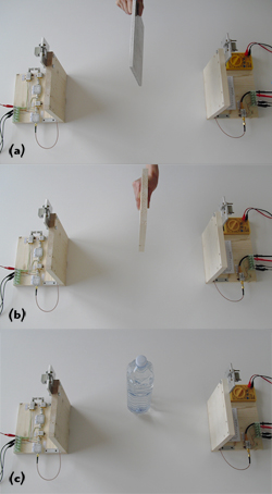
Figure 7 Propagation through materials; metal plate(a), wooden plate (b), water bottle (c).
Polarization
As with antenna gain, the analogy with visible light is quite useful. In fact, polarized sunglasses and polarized camera filters are well known examples. The setup is similar to the one shown in Figure 4, but in this case one of the antennas is rotated of an arbitrary angle, up 90 degrees. With the antennas cross-polarized, the signal received is very low and the buzzer does not work. With the antennas co-polarized, the signal received is high and the buzzer sounds. Data collected with the multimeter shows a 30 dB difference in power between the two configurations.
Propagation Through Materials
One of the most spectacular aspects related to microwave propagation is its interaction with obstacles. To better illustrate this, the analogy with the visible light is fully exploited. The setup shown in Figure 7 is similar to that of Figure 4, but with an obstacle placed between the transmit and receive antennas. A thin metal plate, Figure 7(a), stops both visible light and microwaves; therefore, power recorded by the digital multi-meter is strongly reduced (with the buzzer, no sound is audible). A thin wooden plate, Figure 7(b), stops visible light but does not materially affect microwaves; therefore, the power recorded by the digital multimeter is only slightly reduced (the same for the buzzer sound). Finally, a bottle of water is used in Figure 7(c). Of course, it is possible to see through a small amount of water while it completely stops microwaves; therefore, the power recorded by the digital multi-meter is strongly reduced (with the buzzer no sound is audible).
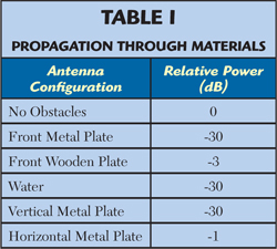
The experiment takes into account not only the nature of obstacles but also their shapes. Moreover, the concept of polarization is recalled. The thin metal plate is placed along the thin side vertically and horizontally in front of the transmitting antenna in Figure 8. When placed vertically the power recorded by the digital multi-meter is strongly reduced, whereas it is almost unchanged (compared to no obstacle at all) when placed horizontally, even though the blocking area is the same in both cases. Results from these experiments are summarized in the Table 1.
Radiation Patterns
This is useful for illustrating that different applications call for different antennas. For example, to illuminate an entire room, a stand-alone bulb is used because it generates light in all directions. Conversely, if only a portion of the room requires light, a reflecting surface may be used in conjunction with the light bulb to concentrate its light in a desired direction. This is illustrated with radiation patterns.
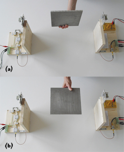
Figure 8 Polarization experiment; vertical plate (a), horizontal plate (b).
Using the setup shown in Figure 9a, the receive section is rotated by using tick marks on a sheet of paper placed beneath the base (not shown in figure). Using the digital multi-meter, this experiment may be repeated twice, first with the SMA-WG transitions and then with one transition replaced by a standard horn antenna. In this way, different radiation patterns are generated with different gain antennas, as shown in Figure 9b. Using the buzzer, it is convenient to consider only one case (e.g., SMA-WG transition) and to limit the explanation to the importance of antenna reciprocal orientation. Data recorded with the digital multi-meter is plotted in Figure 10.
Figure 9 Radiation patterns; setup (a), measured patterns (b).
Radar
In order to avoid the use of costly transmit/receive devices (e.g. circulators), a bi-static radar is used (see Figure 10). The transmitting and receiving sections are set at an angle with respect to each other and power level detected by the digital multimeter is recorded. A target (e.g., a metal or wooden plate) is moved between the two antennas while varying its orientation. Sample data shows up to a 5 dB increase in received power in the presence of the metal plate. This demonstrates that material, shape and orientation are key parameters for target recognition using a radar system.
Dissemination and Educational Impact
This system has been used in a number of different events since its development in 2010. In particular, they can be grouped into two categories: dissemination activities, mainly intended for children, science show and academic open days, and educational activities, mainly intended for under-graduate students in the framework of academic courses.
For dissemination activities, the interest from the public has been enthusiastic, with many questions on the use of microwaves in everyday life. The system provides an easy-to-understand approach to difficult topics and has been clarifying misconceptions about microwaves and EM fields. The success of these events is demonstrated by the number of people attending them. In October 2011 and in October 2012, the system was presented at BergamoScienza (Bergamo, Italy),25 an Italian national science show with around 100,000 attendees over a period of two weeks, in the framework of experiments on EM and mechanical waves prepared by the University of Pavia. The presentation of the system was followed by more than 3,000 people each year. In addition, during 2011 and 2012 the system was presented to around 2,000 children with dedicated events at schools, and to the faculty of engineering of the University of Pavia. Finally, the system has been presented since 2010 to tens of thousands of high-school students in the framework of open days organised by the University of Pavia in order to attract new students.26 The system was part of a set of events promoted by the Department of Electronics to stimulate high-school students toward engineering encouraging STEM careers.
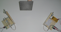
Figure 10 Radar experiment.
In the framework of educational activities, during the academic year 2011/12 and in the academic year 2012/13 the system has utilized as extra activity for the under-graduate students of the class on Electromagnetic Fields students of the course on Electronics and Computer Engineering. The principal aim has been to aid student comprehension and provide experimental evidence of the equations studied during standard lectures. Student feedback has been enthusiastically positive.
Conclusion
A new approach based on hands-on experiments teaches microwaves and EM theory and stimulates interest in these topics. The goal is to efficiently and effectively provide educational and dissemination activities. The intended audience spans from children to high-school students, from science shows to under-graduate and graduate students.
The system is designed to explain different microwave phenomena both qualitatively and quantitatively, according to the educational level of the audience. The experimental setup is not designed to demonstrate a specific phenomenon but, instead, can be used to demonstrate several different concepts, tailored to the educational level of the audience. The equipment uses inexpensive, commercially available, general-purpose devices that limit system cost and enhance reproducibility. This is particularly attractive for most high-school and university laboratories, furthering the dissemination of a microwave education to students and society, and providing a means to attract students toward scientific educational paths. It has been used since 2010, receiving great interest from the general public (science shows, children, high-school students) and from under-graduate and graduate students.
Acknowledgment
The author wishes to thank Prof. Marco Bressan, Prof. Maurizio Bozzi and Prof. Carla Vacchi for providing the data related to attendance during dissemination and educational activities, Prof. Luca Perregrini for useful discussions and the IEEE Antennas and Propagation Society for its contribution to system development in the framework of the AP-S 2010 Student Design Contest.
References
- W. Menzel, “Microwave Education Supported by Animations of Wave Propagation Effects,” IEEE Transactions on Microwave Theory and Techniques, Vol. 51, No. 4, April 2003, pp. 1312-1317.
- G. Weinberger, “The New Millennium: Wireless Technologies for a Truly Mobile Society,” IEEE International Solid-State Circuits Conference Digest, February 2000, pp. 20-24.
- K.C. Gupta, T. Itoh and A.A. Oliner, “Microwave and RF Education – Past, Present, and Future,” IEEE Transactions on Microwave Theory and Techniques, Vol. 50, No. 3, March 2002, pp. 1006-1014.
- G.C. Orsak, “Guest editorial. K-12: Engineering’s New Frontier,” IEEE Transactions on Education, Vol. 46, No. 2, May 2003, pp. 209-210.
- M. Mazanek, M. Polivka, P. Cerny, P. Piksa and P. Pechac, “Education in Antennas, Wave Propagation and Microwave Techniques,” 18th International Conference on Applied Electromagnetics and Communications, October 2005, pp. 1-4.
- M.L.D. Lumori, and E.M. Kim, “Engaging Students in Applied Electromagnetics at the University of San Diego,” IEEE Transactions on Education, Vol. 53, No. 3, August 2010, pp. 419-429.
- A.D. Wunsch, “The Receiving Antenna: A Classroom Presentation,” IEEE Antennas and Propagation Magazine, Vol. 53, No. 4, August 2011, pp. 179-187.
- D.C. Chang, “Engineering Education: Where Do We Go From Here?” IEEE Antennas and Propagation Magazine, Vol. 43, No. 6, December 2001, pp. 114-116.
- W.J.R. Hoefer, “The Effective Use of Computer Modeling and Visualization in Microwave Education,” 29th European Microwave Conference, Vol. 2, October 1999, pp. 86-89.
- A.S. Daryoush, “Microwave Engineering Education Using Web-Based Instruction,” IEEE Microwave Magazine, Vol. 2, No. 2, June 2001, pp. 114-118.
- S. Selleri, “A MATLAB Experimental Framework for Electromagnetic Education,” IEEE Antennas and Propagation Magazine, Vol. 45, No. 5, October 2003, pp. 86-90.
- S. Toutain, C. Person and J.P. Coupez, “Electromagnetic Theory, CAD and Experimental Approach Bases of an Efficient Education in Microwave and RF Techniques,” 31st European Microwave Conference, October 2001.
- J.P. Becker, “Using Antenna Arrays to Motivate the Study of Sinusoids,” IEEE Transactions on Education, Vol. 53, No. 2, May 2010, pp. 209-215.
- D.M. Pozar, “A Modern Course in Antenna Theory and Design,” IEEE Transactions on Education, Vol. 26, No. 1, February 1983, pp. 16-21.
- G.R. Branner, “An Elective Microwave Course Sequence with Integrated Laboratory,” IEEE Transactions on Education, Vol. 33, No. 1, February 1990, pp. 145-148.
- S.V. Hum and M. Okoniewski, “A Low-Cost Hands-On Laboratory for an Undergraduate Microwave Course,” IEEE Antennas and Propagation Magazine, Vol. 49, No. 3, June 2007, pp. 175-184.
- B.C. Brown, F.G. Goora and C.D. Rouse, “The Design of an Economical Antenna-Gain and Radiation-Pattern Measurement System,” IEEE Antennas and Propagation Magazine, Vol. 53, No. 4, August 2011, pp. 188-200.
- A. Temme, D. VanderLann and S. Zajac, “Radiation Patterns on a Budget: IEEE AP-S Student Design Challenge 2011,” IEEE Antennas and Propagation Magazine, Vol. 53, No. 5, October 2011, pp. 166-175.
- V. Picco and K. Martin, “An Automated Antenna Measurement System Utilizing Wi-Fi Hardware,” IEEE Antennas and Propagation Magazine, Vol. 53, No. 6, December 2011, pp. 173-184.
- A.J. Hempy, M.P. Civerolo and D.Y. Arakaki, “Design and Assembly of an Antenna Demonstration System,” IEEE Antennas and Propagation Magazine, Vol. 54, No. 2, April 2012, pp. 209-219.
- B. Bauman, A. Christianson, A. Wegener and W.J. Chappell, “Dynamic Visualization of Antenna Patterns and Phased-Array Beam Steering,” IEEE Antennas and Propagation Magazine, Vol. 54, No. 3, June 2012, pp. 184-193.
- E.L. Burks, “The Junior High Years: A Time for Beginning Engineering Orientation,” IEEE Transactions on Education, Vol. 18, No. 1, February 1975, pp. 15-20.
- W. Shyr, “Integrating Laboratory Activities Into a Junior High School Classroom,” IEEE Transactions on Education, Vol. 53, No. 1, February 2010, pp. 32-37.
- C.A. Balanis, Antenna Theory: Analysis and Design, Wiley & Sons, Hoboken, NJ, 2005.
- BergamoScienza official website, www.bergamoscienza.it, accessed October 2012.
- University of Pavia official website, www.unipv.eu, accessed October 2012.

Marco Pasian received his PhD in electronics and computer science from the University of Pavia, Pavia, Italy, in 2009, where he is now Research Fellow of the Microwave Laboratory. He was with the European Space Agency, Germany, with Carlo Gavazzi Space, Italy and with the TNO, Defence, Security and Safety, The Netherlands in 2004, 2005 and 2008, respectively. His main research interests are in microwave components and antennas for space applications, and in planar technologies on innovative materials. Dr. Pasian is a member of the EuMA and IEEE.