
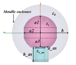
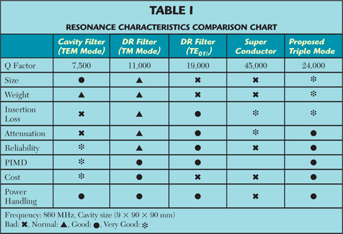
Figure 1 Spherical dielectric resonator with alumina support in a metallic enclosure.
A triple-mode bandpass/bandstop filter uses a high-Q spherical dielectric resonator that supports triply degenerate TE01 modes along three orthogonal axes. Coupling structures based on metallic plates inside the spherical enclosure are also introduced. Due to cross coupling, the proposed bandpass filter (BPF) has an asymmetric response with three controllable transmission zeros, one of which can be located very close to the passband edge to provide an extremely sharp skirt characteristic. In addition, the proposed flexible coupling mechanism allows for realization of a bandstop filter by simply modifying the configuration of the coupling structure. A three-pole single cavity BPF operating at 863 MHz with bandwidth of 14 MHz is designed, simulated and fabricated. Measured results show 0.1 dB insertion loss within the passband and 31 dB rejection 2 MHz away from the lower passband edge.
The dielectric resonator filter is widely used in satellite and mobile communication systems due to its compact size, high performance and superior temperature stability. The TE01δ mode is the fundamental resonant mode of a dielectric resonator and has been extensively studied for the design of single-mode dielectric loaded cavity bandpass filters (BPF).1,2 In these designs, the recommended ratio of the dielectric height over diameter is 1:2.2|3.0 for both optimum Q and minimum interference from spurious modes. This puts a constraint on compactness, especially for low frequency applications.
In recent years, wireless communication systems have evolved to have a distributed base transceiver station (BTS) system architecture employing a remote radio head (RRH) and base band unit (BBU).3 This requires more compact high performance BPFs utilizing dual-mode and multi-mode techniques.4-9 A typical dual-mode dielectric resonator filter using the HE11δ degenerate mode was first reported by Fiedziuszko.4 With proper diameter/length ratio of dielectric resonator, the HE11δ mode and TM01δ mode can resonate at the same frequency to form a triple-mode BPF.5 A triple-mode BPF employing the triply degenerate TE01δ mode in a cubical dielectric loaded cavity resonator was described by Walker and Hunter.6 All of these, however, use cylindrical or rectangular dielectric resonators. The spherically shaped dielectric resonator has received less attention. In addition, these designs rely on either the machining of chamfers in dielectric resonator7,8 or the use of screws9 to control the coupling between degenerate modes. This increases the complexity of fabrication and tuning.
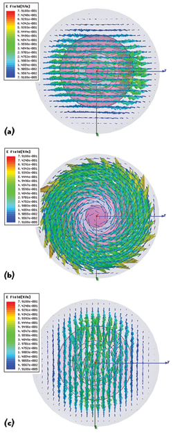
Figure 2 Top view of the electric field distribution along the three axes, TE01δX at 845.66 MHz. (a), TE01δY at 845.69 MHz (b), TE01δZ at 852.76 MHz (c).
In this article, we introduce a triple-mode bandpass/bandstop filter using a high-Q spherical dielectric loaded cavity resonator and new coupling structures located inside the cavity. The coupling structures need no additional space or screws, and have several configurations for generating cross coupling to realize multiple controllable transmission zeros. In addition, one of the transmission zeros can be located very close to the passband edge, producing an extremely sharp rejection characteristic.
A test resonator exhibits a high unloaded Q of 19600 in the 860 MHz band. Fabricated filters, using temperature-stable dielectric material KMW ZT with a dielectric constant of 46,10 can be reduced in size by 40 percent compared to their single-mode counterparts while providing similar performance.
Triple-Mode Dielectric Resonator
It is well known that a dielectric resonator with free-space boundaries can resonate in various modes according to its shape and size. A multi-mode dielectric resonator can support several operating modes resonating at the same frequency, a property that is used to construct multi-mode BPFs. Due to perfect symmetry in all three dimensions, the spherical dielectric resonator is superior to a cylindrical or rectangular resonator and exhibits a very high unloaded Q.
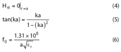
The resonant frequencies of the spherical dielectric resonator can be calculated by solving Maxwell’s equations based on r, θ, φ in the spherical coordinate system. The lowest TE01δ mode is defined by11,12
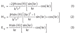
If the radius of the spherical dielectric resonator is a and the outer surface is considered a perfect magnetic boundary, then ka ≈ 2.74,12 and
From equation 6, the value of a is based on the desired center frequency and the dielectric material. As illustrated in Figure 1, the spherical dielectric resonator is placed at the center of an air-filled spherical metallic enclosure with radius of b = 45 mm on an alumina support with permittivity of εr_as = 9, height h_as = 20 mm and radius a_as = 13 mm. Due to its symmetry, the dielectric sphere can sustain three orthogonal degenerate modes – TE01δX, TE01δY and TE01δZ – along the x-, y- and z-directions. The sphere’s surface along the z-axis is cut a little, so the radius in the xy-plane is reduced from a1 to a2 for fine frequency tuning of the TE01δZ mode without significantly affecting the other two modes. The bottom of the dielectric sphere is also cut slightly to fix it concentrically, and can be used to finely control the resonant frequencies of the TE01δX and TE01δY modes.
Figure 2 is the simulated electric field distribution along the three axes of the dielectric sphere with dimensions of a1 = 29.4 mm, a2 = 27.3 mm and a3 = 22.5 mm. These dimensions are refined and optimized using a full-wave simulator to yield the exact center frequency of the triple-mode filters. The corresponding resonant frequencies are f1 (TE01δX) = 845.66 MHz, f2 (TE01δY) = 845.69 MHz and f3 (TE01δZ) = 852.76 MHz. The dielectric constant of the resonator is 46 and the unloaded Q is 19600.
The dielectric resonator has very high unloaded Q, determined by the material powder and the fabrication process. Another important material property is the temperature coefficient of the resonant frequency. The filters used in high power applications such as base station wireless communication and satellite communication systems are subjected to large temperature variations. In addition, due to the diversity of base station geographic locations, filters must operate various ambient conditions.13 Table 1 compares the performance of the triple-mode filter described here with filters employing other technologies.
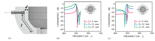
Figure 3 Schematic of the open-ended input/output coupling structure (a), coupling plates with opposite direction (b), coupling plates with identical direction (c).
Dielectric Resonator Filter Design
Triple-Mode Bandpass Filter
The concept is verified with a single cavity filter employing the three degenerate TE01d modes in the x-, y- and z-directions, yielding a three-pole filter. The desired center frequency is 863 MHz with 14 MHz bandwidth. The filter is designed using the well-known coupling coefficients/external Q method. The coupling coefficients and external Q are given by the following:14
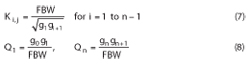
Figure 4 Schematic of the short-ended input/output coupling structure (a), external Q (b), coupling coefficient K (c).
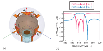
Figure 5 Triple mode BPF coupling network (a), simulated frequency response (b).
where gi is the 0.01 dB Chebyshev lowpass prototype element and FBW is the fractional bandwidth.
The input/output structure is designed to provide the required external Q. In general, two kinds of input/output configurations, open-ended and short-ended, are commonly used. Figure 3a shows the schematic of an open-ended port coupling configuration. In this case, the length l of the coupling plate, as well as the distance d from the dielectric resonator, determine the amount of input/output coupling. When the two coupling plates have opposite directions, as shown in Figure 3b, the transmission zero due to input/output coupling is located above the passband. If the output plate is now reversed in direction, as illustrated in Figure 3c, the transmission zero for the lower stopband can be achieved. The frequency of the transmission zero can be controlled by the plate length l. We use the short-ended configuration, as shown in Figure 4a, because the open-ended structure is difficult to keep fixed and coupling plate angle variation influences coupling strength. In addition, the short-ended configuration is suitable for high power applications like front end unit (FEU) in BTS due to good heat dissipation properties.
Since the short-ended configuration is a fixed structure, the length of the coupling plate cannot be tuned. The required external Q can be achieved by adjusting the plate width (w1) and distance d. Figures 4b and c show external Q and coupling coefficient based on physical parameters d, w1, w2 and l2 (see Figure 5). It can be seen that external Q increases with larger d, resulting in weaker input/output coupling. Beyond a certain value of d, however, the wider the coupling plate, the smaller the external Q.
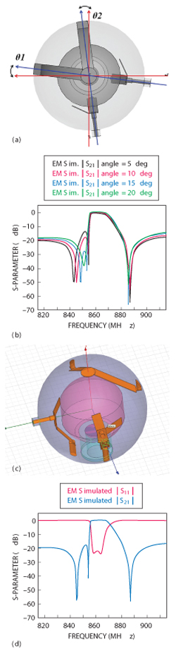
Figure 6 Cross coupling between the TE01δX and TE01δY modes (a), simulated frequency responses for varying θ1= θ2 = θ (b), completed triple-mode BPF model in HFSS (c), simulated frequency response (d).
Because each cavity contains three resonances, a controllable coupling scheme is required. Unlike the conventional method, using machining chamfers or screws, a new structure based on metallic coupling plates is introduced in this design. The coupling plates are located inside the cavity, so no additional space is needed. Since all three of the TE01δ degenerate modes are orthogonal to each other, as shown in Figure 5a, the input/output plates are positioned at 90° to excite the resonance. For coupling between modes TE01δX and TE01δZ, two coupling plates with length of l2 and width of w2 are connected to the input/output plates along the xy-plane. The resonant modes TE01δZ and TE01δY are coupled using another two coupling plates with length of l3 and width of w3. They are connected at the top center of the cavity, also separated by 90°. Ninety degree separation is essential to couple the orthogonal modes. Parameter d2 is the distance between the connecting point and the cavity top. Figure 5b shows the simulated frequency response; a three-pole filter is achieved and there is a transmission zero on the upper stopband due to direct coupling between the source and load.
Introducing a rotation angle (θ) between the two top coupling plates, as depicted in Figure 6a, can improve the left slope performance. Figure 6b shows how the skirt characteristics are improved as a function of θ. Due to this rotation angle, cross coupling between the TE01δX and TE01δY modes is generated, causing another two transmission zeros to appear. This cross coupling can be controlled by θ without significantly affecting direct-coupling. The positions of the transmission zeros can be adjusted while maintaining constant passband bandwidth. In addition, the upper stopband transmission zero is attributed to the input/output cross coupling, so its location also remains nearly constant with varying θ. The simulated results are illustrated in Figure 6b. Figure 6c shows the completed triple-mode BPF model in HFSS and corresponding frequency responses are given in Figure 6d. Optimized design parameters are d = 3.25 mm, d2 = 10 mm, w1 = 7.5 mm, w2 = 7.5 mm, w3 = 8 mm, l2 = 12.5 mm, and l3 = 45 mm.
Equivalent Circuit
Figure 7a shows the coupling scheme. The solid line represents direct coupling, with cross coupling indicated by the dotted line. As described above, the input/output coupling results in one transmission zero above the passband. The other two transmission zeros in the lower stopband are attributed to cross coupling between the TE01δX and TE01δY modes. It should be noted that cross coupling between the TE01δX mode and load is also characterized. With the effect of this coupling taken into consideration, a sharper slope of the BPF lower stopband can be realized, leading to better agreement between the computed and measured responses. Figure 7b is the equivalent circuit model of the BPF using L and C lumped elements. The circuit model is simulated using GENESYS, with results shown in Figure 7c.
Various Notch Designs
The coupling mechanism using metallic plates has the advantage of flexibility, which allows for realization of various notch designs. By simply modifying the configuration of the coupling structure, coupling between the three degenerate modes can be arbitrarily controlled, resulting in various stopband characteristics. To demonstrate this property, Figure 8a and b are two possible coupling configurations and their corresponding frequency responses, illustrating that the positions of transmission zeros can be freely determined.
Triple-Mode Bandstop Filter
An approach to designing bandstop filters using directly coupled resonators is described by Cameron et al.15 This method makes the techniques used for bandstop filter design and construction very similar to those used for the BPF. Based on this method, by simply arranging the coupling plates in other configurations, the triple-mode BPF can be converted to bandstop filter. Figures 9a and b show two realizable configurations. Good performance is observed in simulation using HFSS, illustrating another advantage of this coupling structure over approaches using coupling screws or machining chamfers.
Experiments
Fabrication and Measurement
Figure 10a shows the fabricated triple-mode BPF loaded with spherical dielectric resonator. Measurements obtained using an Agilent E5871 VNA are in good agreement with the HFSS simulation results shown in Figure 10b. The BPF exhibits a low insertion loss of 0.1 dB and a return loss of nearly 20 dB across the passband. Three transmission zeros generated due to cross coupling are located at 843, 854 and 885 MHz with attenuation of 55, 31 and 53 dB, respectively. Rejection of 31 dB at 2 MHz away from the lower band edge is due to the second transmission zero. This characteristic is very attractive for wireless communication systems where interference from an adjacent channel must be cut-off in the very narrow guard-band, and where co-siting of different services in the same band is needed.
Power Handling Capability
The triple-mode BPF has high power handling capability and can be used in a BTS for CDMA and LTE communication systems. Average power handling of the fabricated BPF is about 100 W, and in experiments, the increase of dielectric resonator temperature is not significant even when the peak power is 1000 W. In addition, the heating-proof effect is also satisfied, so its power handling capability is at the same level as that of existing single TE01dmode BPFs.
Spurious
The proposed triple-mode BPF demonstrates nearly the same behavior of the spurious performance when compared with the single TE01δ mode BPFs, but leads to a significant reduction in size.
Conclusion
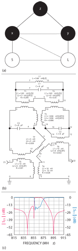
Figure 7 BPF coupling scheme (a), equivalent circuit with cross coupling (b), simulated frequency response of the equivalent circuit (c).
A novel triple-mode high-Q spherical dielectric loaded cavity BPF, based on the three degenerate TE01dmodes and a new coupling structure, demonstrates low insertion loss and sharp passband skirts due to cross coupling. A triple-mode single cavity BPF in the 860 MHz band provides design verification. It features significant size and mass reduction, and much higher Q when compared with conventional dielectric resonator filters and can be adapted for use in various applications by changing transmission zero positions or by changing its type from bandpass to bandstop.
Acknowledgment
This research was supported by the R&D program supervised by the Korea Communications Agency (KCA) (KCA-2012-12-911-01-109).
References
- J.F. Liang and W.D. Blair, “High-Q TE01 Mode DR Filters for PCS Wireless Base Stations,” IEEE Transactions on Microwave Theory and Techniques, Vol. 46, No. 12, December 1998, pp. 2493-2500.
- K. Wakino, T. Nishikawa and Y. Ishikawa, “Miniaturization Technologies of Dielectric Resonator Filters for Mobile Communications,” IEEE Transactions on Microwave Theory and Techniques, Vol. 42, No. 7, July 1994, pp. 1295–1300.
- A. Ghosh, N. Mangalvedhe, R. Ratasuk, B. Mondal, M. Cudak, E. Visotsky, T.A. Thomas, J.G. Andrews, P. Xia, H.S. Jo, H.S. Dhillon and T.D. Novlan, “Heterogeneous Cellular Networks: From Theory to Practice,” IEEE Communications Magazine, Vol. 50, No. 6, June 2012, pp. 54-64.
- S.J. Fiedziuszko, “Dual-Mode Dielectric Resonator Loaded Cavity Filters,” IEEE Transactions on Microwave Theory and Techniques, Vol. 30, No. 9, September 1982, pp. 1311-1316.
- W.C. Tang, J. Sferrazza, B. Beggs and D. Siu, “Dielectric Resonator Output Multiplexer for C-Band Satellite Applications,” IEEE MTT-S International Microwave Symposium Digest, June 1985, pp. 343-345.
- V. Walker and I.C. Hunter, “Design of Triple Mode TE01δ Resonator Transmission Filters,” IEEE Microwave and Wireless Components Letters, Vol. 12, No. 6, June 2002, pp. 215-217.
- I.C. Hunter, J.D. Rhodes and V. Dassonville, “Triple Mode Dielectric Resonator Hybrid Reflection Filters,” IEEE Proceedings on Microwaves, Antennas and Propagation, Vol. 145, No. 4, August 1998, pp. 337–343.
- H. Salehi, T. Bernhardt, T. Lukkarila and S. Amir, “Analysis, Design and Applications of the Triple-Mode Conductor-Loaded Cavity Filter,” IET Microwaves, Antennas & Propagation, Vol. 5, No. 10, July 2011, pp. 1136-1142.
- L.H. Chua and D. Mirshekar-Syahkal, “Analysis and Design of Three Transmission Zeros Bandpass Filter Utilizing Triple-Mode Dielectric Loaded Cubical Cavity,” IEEE MTT-S International Microwave Symposium Digest, Vol. 2, June 2003, pp. 937-940.
- Black Hole Filter (Triple Mode Technology. Retrieved November 27, 2013 from KMW RF and Microwave Products Website: www.kmw.co.kr/eng/rf/03_01_00.html.
- D. Kajfez and P. Guillon, Dielectric Resonators, Artech House, Norwood, MA, 1986.
- C. Hunter, Theory and Design of Microwave Filters, IEE, London, UK, 2001.
- S.J. Fiedziuszko, I.C. Hunter, T. Itoh, Y. Kobayashi, T. Nishikawa, S.N. Stitzer and K. Wakino, “Dielectric Materials, Devices, and Circuits,” IEEE Transactions on Microwave Theory and Techniques, Vol. 50, No. 3, March 2002, pp. 706-720.
- J.S.G. Hong and M.J. Lancaster, Microstrip Filters for RF/Microwave Applications, Wiley-Interscience, New York, NY, 2001.
- R.J. Cameron, M. Yu and Y. Wang, “Direct-Coupled Microwave Filters With Single and Dual Stopbands,” IEEE Transactions on Microwave Theory and Techniques, Vol. 53, No. 11, November 2005, pp. 3288- 3297.
Nam-Shin Park received the B.E degree from the Soonchunhayng University, Asan, Korea, in 1994, and is currently working toward the M.S. degree in management of technology at Sogang University, Seoul, Korea. Since 1993, he has been working with the RF UNIT Group, R&D Center, KMW Inc., Hwasung, Korea, as a group manager. His interests include microwave filter, dielectric resonator and filter, high-Q and multiple mode resonator and filter miniaturization.
Don-Yong Lee received the B.E degree from the Seoul National University of Science and Technology, Seoul, Korea, in 1998. Since 1997, he has been working with the RF UNIT Group, R&D Center, KMW Inc., Hwasung, Korea, as a principal research engineer. His interests include microwave circuits, cavity and ceramic filters and power handling capability for wireless base station.
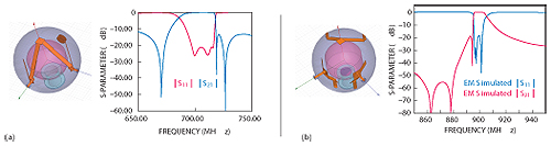
Figure 8 Various notch designs are possible by rearranging the coupling configuration.
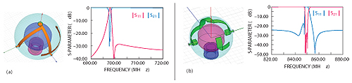
Figure 9 Bandstop filters and corresponding simulated frequency responses.
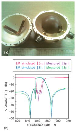
Figure 10 Fabricated triple-mode BPF (a), measured and simulated frequency responses (b).
Byung-Chul Kim received the B.E. degree from the University of Seoul, Seoul, Korea, in 1992, and is currently working toward the M.S. degree in Management of Technology at Sogang University, Seoul, Korea. Since 1997, he has been working with the RF UNIT Group, R&D Center, KMW Inc., Hwasung, Korea, as a principal research engineer. His interests include filter related product and radio communication.
Jung-Hee Won received the B.E degree from the Kumoh National Institute of Technology, Gumi, Korea, in 2000. In 2000, he joined the RF UNIT Group, R&D Center, KMW Inc., Hwasung, Korea, where he is currently engaged in research and development on microwave filters and units as a senior research engineer. His research interests include microwave cavity and dielectric filter for wireless base stations and co-siting.
In-Ho Na received B.S. and M.S. degrees in electronic engineering from Soonchunhyang University, Asan, Korea, in 2007 and 2009, respectively. In 2012, he joined the strategy business group, R&D Center, KMW Inc., Hwasung, Korea, as an assistant research engineer. His interests include RF components, front end devices and small cell base station.
Geon-Ho Jang received B.E. and M.S. degrees in information telecommunication engineering from the University of Incheon, Incheon, Korea, in 2009 and 2011, respectively. In 2011, he joined the RF UNIT Group, R&D Center, KMW Inc., Hwasung, Korea, where he is currently engaged in research and development on microwave filters. His interests include microwave passive components, antennas and metamaterials.
Young-Ho Cho received B.Sc and PhD degrees in electronic engineering from Sogang University, Seoul, Korea, in 2005 and 2012, respectively. From September 2012 to March 2013, he was a post-doctoral researcher with Sogang University. He is currently a post-doctoral researcher with the University of California at San Diego (UCSD), La Jolla, CA, USA. His research interests include RF filters, tunable RF components and RF systems.
Xu-Guang Wang received the B.Sc. degree in electronic engineering from Qingdao University, Qingdao, China, in 2006, the M.Sc. degree in radio science and engineering from Korea Maritime University, Busan, Korea, in 2008, and PhD degrees in electronic engineering from Sogang University, Seoul, Korea, in 2013, respectively. His research interests include RF/microwave filters, and associated passive and active circuits.
Sang-Won Yun received B.Sc. and M.Sc. degrees in electronic engineering from Seoul National University, Seoul, Korea, in 1977 and 1979, respectively, and the PhD degree in electrical engineering from the University of Texas at Austin, Austin, TX, USA, in 1984. Since 1984, he has been a professor with the department of electronic engineering, Sogang University, Seoul, Korea. From October 2009 to September 2011, he was with the Korea Communications Commission (KCC), as a project manager. His research interests include microwave and millimeter-wave devices and circuits.