
Today, more than ever before, electromagnetic (EM) simulation is embraced in the research and design of technologies ranging from RFID tags, to radar systems on ships and most things in between. Increasingly, simulation is applied as a means for digital prototyping early in the product development cycle. It also offers a virtual test platform for scenarios where measurement of the actual usage environment might be challenging or impossible, e.g., a cardiac pacemaker, or lightning striking an airplane. The challenge in these cases is how to generate dependable simulation results.
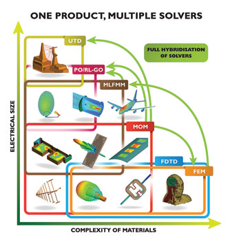
Figure 1 FEKO has pioneered the development of multiple CEM solvers, and the hybridisation thereof, enabling solutions for a broad scope of applications and seamless cross-validation.
The FEKO approach is to provide all of the EM solvers in a single license, rather than licensing each solver individually. This broadens the scope of how customers are able to solve problems. The advantage of this approach is that, in the absence of measurements, a good correlation between simulation results using different solvers can give the user confidence and certainty in their models.
EMSS’s belief is that no single computational EM (CEM) method is capable of solving the whole spectrum of problems which is why different CEM methods are normally applied to specific applications. By hybridizing different solvers, it is possible to further combine the advantages of these individual methods to solve an even broader scope of problems, as is illustrated in Figure 1.
With the introduction of fully integrated finite difference time domain (FDTD) and multilevel fast multipole/physical optics (MLFMM/PO) hybrid solvers, FEKO’s Suite 7.0 release will take the next step toward a complete solution. Examples follow to illustrate the features and capabilities of the new release.
EMP and Lightning Analysis
A scenario where making field measurements is challenging is the study of the propagation of an electromagnetic pulse (EMP) or a lightning strike on a building. Although the pulse waveforms for EMP and lightning are not the same, the nature of the problem is similar. The goal is to understand the transient fields in order to shield sensitive electronic equipment.
The building structure (see Figure 2) is simulated with FDTD using a typical pulse. The cross-validation is done with the frequency domain method of moments (MoM) at specific frequencies within the spectrum of the pulse. Despite solving the complex geometry with time and frequency domain methods, the results agree very well.
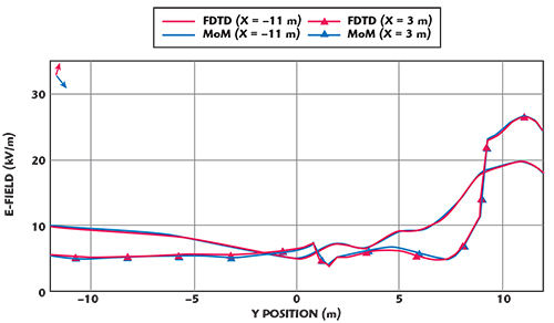
Figure 2 Comparison of FDTD and MoM results of the E-field for the two storey building. The field distribution is also shown at 50 MHz.
Microwave Filter Design
The design of microwave filters can be automated using optimization routines. In addition to understanding the structure, this is an attractive approach to reduce the number of prototype iterations. In this case, the S-parameters are calculated for a filter constructed from dielectrics in an evanescent-mode waveguide (see Figure 3). The two parallel cut-off paths are realized by a partial H-plane bifurcation [Shigesawa, “Two-path cut-off waveguide dielectric resonator filters”].
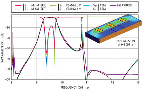
Figure 3 Comparison of the S-parameters for a dielectric resonator and the field distribution in the transmission band at 9.4 GHz.
The structure was simulated using the following three methods: MoM (using the Surface Equivalence Principle for the dielectrics), hybrid FEM/MoM (MoM applied to the waveguide and finite element method FEM to the dielectrics) and FEM only. Not only do the simulation results correspond exceptionally well with each other, but also with the measurements.
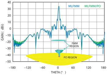
Figure 4 Comparison of the gain of a Cassegrain reflector solved with MLFMM and hybrid MLFMM/PO.
A Cassegrain Reflector
Designing electrically large reflectors to meet gain, beamwidth and sidelobe requirements is a challenging task, even more so when complex feed horns are used that require many unknowns in the MoM region. FEKO’s new hybrid MLFMM/PO solver is ideally suited to this type of problem because of the huge memory saving offered by MLFMM (when compared to standard MoM).
A Cassegrain reflector with a main reflector diameter of 25λ, operating at 10 GHz, and a corrugated horn feed (see Figure 4) is used to illustrate how this method can be applied–MLFMM for the horn and sub-reflector, PO for the main reflector with bi-directional coupling. The results are compared with the full-wave solution of the whole structure which is solved with MLFMM alone. There is excellent agreement between the full-wave solution, where the MLFMM is applied to the total structure, and the hybrid MLFMM and PO solution. It is only behind the reflector where small differences can be observed.
Simulations have also shown that ignoring the coupling between the feed, the sub-reflector and the main reflector can lead to significant inaccuracies. Using the radiation pattern of the horn and sub-reflector as a feed has been shown to be extremely efficient approximation, but care should be taken with unaccounted for coupling effects.
Specialized Implementations
In addition to the broad range of solvers offered in FEKO, other specialized implementations are available. These include the multi-conductor transmission line (MTL) model which is used to study radiation/irradiation/bi-directional coupling for arbitrary cable cross-sections.
Many of FEKO’s solution methods (MoM, MLFMM, FEM, etc.) may be used to compute the external fields and currents that couple to or from such complex cable bundles. Special solutions are available for the efficient analysis of thin dielectric sheets and periodic structures. This can be applied when solving frequency selective surfaces, finite arrays and antennas integrated into glass windscreens.
Characteristic mode analysis (CMA) allows the calculation of natural current modes supported by a structure. These modes give insight into the fundamental radiation and cross-coupling characteristics of the structure, which can then be used to obtain certain design objectives. For example, the position of an antenna on a structure can be chosen to excite a specific mode, which will in turn create a desired radiation pattern.
It is inevitable that the nature of the problems that need to be simulated will become increasingly more complex. Release 7.0 addresses current issues and FEKO intends to provide solutions to tackle new challenges in the future.
FEKO is a product of EM Software & Systems-S.A.
(Pty) Ltd., Stellenbosch, South Africa,
+27 21 831 1500,
www.feko.info