
Changes in ambient temperature significantly affect crystal oscillator frequency stability due mainly to the frequency vs. temperature characteristic of the crystal resonator. Frequency stability of the oscillator can be greatly improved by using an oven-control system that accurately maintains the temperature of the resonator and its sustaining circuitry. But very high stability of an oven-controlled crystal oscillator (OCXO) is attained at the expense of a relatively large size/high power oven to maintain the temperature of a packaged resonator, while oscillator circuitry is poorly isolated from the environment. Although there have been improvements in the basic performance of high-end OCXOs over recent years, the power consumption and packaging size of even the most advanced designs have remained at about 1 W and 5 cm3.
In the late 70s, an alternative OCXO concept was proposed based on the internally heated resonator (IHR) that integrates the heating system with the crystal plate within the resonator’s vacuum-sealed package. Elimination of the bulky external oven and improved thermal isolation of the internal heating structure from the environment promised a radical reduction in power consumption, size and warm-up time. Nevertheless, its adoption has been delayed by a few practical challenges:
- Providing uniform heating of the crystal plate in a small resonator volume with sufficient mechanical durability and low environmental thermal loss.
- Sustaining a deep vacuum within the IHR volume.
- Minimizing the effect on frequency of the external, unheated, circuitry.
This article outlines methods used to address these challenges and realizes a new class of high performance OCXOs.
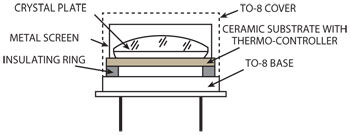
Figure 1 Typical construction of an IHR built in a TO-8 package.
Internally Heated Resonator Construction
A standard TO-8 cold-weld holder, commonly used for packaging of conventional high precision crystals, is chosen to ensure reliability of the vacuum seal and accommodate a 10 mm crystal plate along with the integrated heating system. Typical construction of the IHR is shown in Figure 1. It contains a supporting structure mounted on the TO-8 base, made of low thermal conductivity materials for thermal isolation of the oven system above it. The integrated oven is implemented on a ceramic substrate bearing the whole thermo-control circuitry with the heater elements and the temperature sensor. The heated substrate provides accurate and uniform warming of the crystal plate at a fixed temperature via mounting clips and a metal screen over the plate surface. This IHR concept is called an indirectly heated resonator, because the heating elements are separated from the plate surfaces. This reduces the sensitivity of the crystal resonant frequency to changes in ambient temperature from coupling of weak thermal flows inside the oven structure to the environment. Due to near perfect thermal isolation of the integrated oven by a deep vacuum inside the TO-8 package and low conductivity of the supporting elements, the IHR design consumes very low power even at low ambient temperatures (see Figure 2).
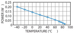
Figure 2 IHR heating power vs. ambient temperature (internal temperature = 90ºC).
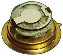
Figure 3 Directly heated IHR.
An alternative IHR concept called directly heated resonator (DHR) is shown in Figure 3. Warming of the crystal plate is accomplished with film heaters deposited directly on the plate surfaces along with the temperature sensor. Strong thermal coupling of the film heaters to the plate surfaces results in extremely fast warm-up of the plate (exceeding 10°C/s), although there are significant thermal gradients produced in the plate during heating. Nevertheless, an optimal choice of heater geometry and use of a stress-compensated SC-cut plate enables the set frequency to be achieved in less than 10 s to 0.1 ppm (i.e., steady state) with sufficient start-up power (see Figure 4).
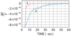
Figure 4 IHR warm-up time using direct heating (1), using indirect heating (2).
Oscillator Circuitry
Sustaining circuitry of miniature OCXOs using the IHR concept must contain a minimum number of electronic components to fit onto the smallest PC boards; ensure steady excitation of the crystal using the SC or other double-rotated cut at the main C-mode, suppress the unwanted B-mode; ensure the lowest phase-noise level and highest spectral purity of the output signal; and, being outside the heated volume, have a minimal influence on oscillator frequency over wide variations of ambient temperature.
Among these requirements, effective suppression of the unwanted B-mode by the oscillator circuitry is the most challenging, since common suppression techniques using LC filtering require additional components and accurate adjustment, while exhibiting noticeable temperature sensitivity that limits oscillator temperature stability. To avoid these issues, we employ an alternative method based on different start-up times of the B- and C-modes in the double-rotated cut crystals, a consequence of substantial differences in their equivalent electrical parameters.
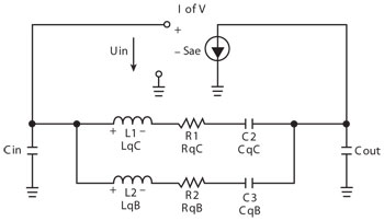
Figure 5 Oscillator equivalent circuit with a dual-mode crystal.
The high frequency model of the sustaining circuitry at excitation of the dual-mode crystal is shown in Figure 5. The rise of B- and C-mode amplitudes during start-up is governed by the expressions:
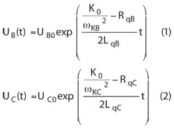
where RqB, LqB and RqC, LqC are equivalent resistance and inductance of the B- and C- modes accordingly.
At a sufficiently high value of the gain factor (K0), the equivalent inductance becomes a determining factor in the rate of amplitude rise. Due to a lower value of inductance for the C-mode (about 75 percent of the B-mode inductance in an SC-cut crystal) its amplitude grows faster, reaching steady state first and suppressing further B-mode growth. This is called “dynamic selection” due to the absence of special filtering elements. It requires minimal PCB space, produces no effect on temperature stability of the sustaining circuitry and needs no elaborate tuning. This technique provides excellent performance in OCXOs utilizing IHR technology.
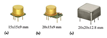
Figure 6 IHR OCXO families: MXO37/8 (a), MXO37/14 (b) and MXO37/R (c).
Realization and Performance
These designs are the basis for three new families of OCXOs (see Figure 6). The smallest, MXO37/8, is a high stability OCXO with the oscillator circuitry built in a TO-8 package and mounted on a DIP8 compatible PC board. The MXO37/14 oscillator and associated electronic elements are packaged with the resonator in a TO-8 package, and with the rest parts on a DIP14 compatible PC board. The MXO37/R oscillators are packaged in a 20 × 20 × 12.8 mm hermetically sealed case.
Even the smallest DIP8 oscillators exhibit high frequency stability and low phase noise at nearly the level of high-end conventional OCXOs, while the larger DIP14 series, accommodating more complex circuitry, provides better temperature stability and can operate at much higher frequencies owing to internal frequency multiplication stages. The larger volume in the MXO37/R series OCXOs allows for additional thermal compensation circuitry, increasing temperature stability to nearly the level of double-oven oscillators.
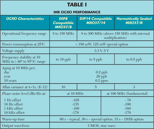
Table 1 summarizes performance achievable from the three OCXO families, demonstrating very high frequency stability and low phase noise in a miniature size with extremely low power consumption. Such properties make these OCXOs excellent solutions for a variety of current applications as well as new developments.
Conclusion
IHR technology has proved to be a powerful enabler for development of a new kind of reference oscillator with excellent frequency stability, low phase noise, small size and low power consumption. Covering a wide range of customer needs, these devices offer an alternative to conventional high-end OCXOs. Potential applications include advanced battery supplies and portable equipment, such as high-end mobile radio, GPS, rescue or geodesic beacons, drone electronics and instrumentation.